Facebook
 Google
 GitHub
 Linkedin
A Software-Configurable SiC MOSFET Gate Driving Approach
Wide bandgap SiC technology plays a key role in the electrification of everything and will soon tackle other major challenges, such as overhauling the grid to achieve omnidirectional power flow.
This article is published by EEPower as part of an exclusive digital content partnership with Bodo’s Power Systems.
SiC MOSFETs are the power switch of choice for high-voltage and high-power applications in traction, distributed energy resources (DERs), onboard chargers (OBCs), medical devices, and more. SiC semiconductors outperform their silicon predecessors in key capabilities ranging from higher operating temperatures, breakdown voltage, and switching speeds to lower RDS(on) and improved thermal performance and ruggedness. The advantages compared to silicon are propelling SiC into a pivotal role in global sustainability initiatives such as electrifying transportation, expanding the EV charging infrastructure, and modernizing the omnidirectional electric grid.
SiC technology is already widely adopted in medium- and high-voltage applications for E-Mobility, industrial, renewables/grid, and other applications. To fully realize its benefits, system developers must first counteract the undesirable secondary effects of its faster switching speeds. Traditional gate drivers are inadequate to address these SiC-related challenges, as SiC-based system designs have increased in complexity. These traditional gate drivers were created for use with much slower silicon insulated-gate bipolar transistors (IGBTs).
SiC-based system developers who want faster time-to-market, flexibility, and improved design capabilities are turning instead to intelligent, configurable digital gate drivers. These drivers also enable them to easily optimize switching performance from the ease and comfort of their keyboards rather than by re-spinning system boards or soldering gate resistors onto them.
Resolving SiC’s Secondary Effects
Designers using SiC technology face dynamic new challenges in efficient driving and safe control of the devices. With SiC switching much faster than silicon, the accompanying faster voltage and current transitions create challenges or secondary effects, which can cause potential noise and electromagnetic interference (EMI) as well as ringing, overvoltage, and overheating. These effects can lead to device breakdown, unwanted noise, lower system performance, and other issues unless developers use careful circuit design and filtering, among other mitigating steps.
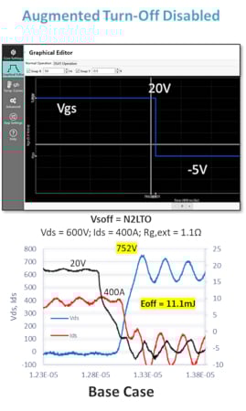
Image used courtesy of Bodo’s Power Systems [PDF]
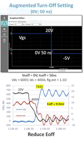
Image used courtesy of Bodo’s Power Systems [PDF]

Figure 1. Comparison of conventional analog gate drive with digital gate drive using configurable profiles. Image used courtesy of Bodo’s Power Systems [PDF]
System designers using silicon IGBTs have not generally had to spend much time mitigating secondary effects like these and could get by using traditional analog gate drivers. Using traditional analog gate drivers with SiC technology causes inefficiencies because of the requirement for significantly faster response time during fault conditions. Analog gate drivers are also difficult to modify to optimize switching operation and performance.
Digital gate drivers solve these challenges while also providing robust short-circuit protection. A software-configurable approach using gate drive profiles is a key element of the latest digital gate drivers. This approach allows digitally configuring SiC power device switching characteristics for the best possible efficiency based on application criteria, ranging from power levels and switching frequencies to load conditions.
Advantages of mSiC and Configurable Augmented Switching Technology
One of the biggest advantages of today’s digital gate drivers is they can be augmented with configurable turn-on and turn-off switching profiles. This enables designers to achieve up to 50 percent lower switching losses and up to 80 percent lower VDS overshoot.
Microchip’s mSiC gate driver solutions with Augmented Switching technology provide gate drive profiles spanning the steps for controlling turn-on and turn-off gate voltages and their durations. Designers can easily and quickly modify these profiles digitally through software to accommodate their specific application needs rather than making hardware changes. The technique also includes independent short-circuit response and robust fault monitoring/detection.
Figure 1 shows how this type of gate drive works to implement configurable turn-off switching. The top image in each column is the graphical editor of the Intelligent Configurable Tool (ICT), and the bottom image is the resultant scope shot with the turn-off waveforms. The left graph shows conventional switching (augmented turn-off is disabled). The middle graph shows the application of one augmented turn-off setting, and the third graph shows a second turn-off option. The conditions in each case were 600 V VDS and 400 A IDS with 1.1 Ω gate resistors.
The third graph shows the desired result: a reduced Vovershoot peak of 712 V along with lower voltage and current ringing. This is achieved by starting with an on-stage voltage of 20 V, proceeding to a configurable intermediate level of 4.5 V, and holding there for 650 nanoseconds (ns) before dropping to the -5 V turn-off voltage. Turn-off energy, which increased to 16 mJ, was traded for reduced Vovershoot and ringing (EMI).
In addition to providing configurable profiles, today’s solutions incorporate additional fault monitoring detection levels and short-circuit response. Together, these capabilities give designers multiple levels of control and protection to ensure safe, reliable operation.
For many designers using SiC MOSFETs, the question isn’t whether to use intelligent digital gate drivers but build one from the ground up for their needs or use a plug-and-play gate driver solution. There are multiple options to consider.
Design Considerations for Implementing an In-House or Plug-and-Play Gate Driver Solution
Developers can create fully functional SiC MOSFET gate driving solutions with software-configurable ±VGS gate voltages. This can be done using digital gate driver cores supported by module adapter boards that facilitate evaluation and development. Complete digital gate driver development kits are also available to accomplish this.
Some system developers do not have the in-house design engineering skills to build their solutions, and time-to-market pressures require a solution that can be implemented more quickly. In these cases, a plug-and-play approach like Microchip’s plug-and-play mSiC gate drivers is available using gate driver boards that work out of the box with pre-configured module settings. These boards are supported by programming kits and ICT software that enable additional optimization as required by the application, whether heavy-duty vehicles and Auxiliary Power Units (APUs) or charging, storage, inverters, and induction heating systems.
Another benefit of plug-and-play gate drivers is that they are already qualified to meet industry-specific standards and are easier to assemble than alternative approaches. They streamline cost and development while removing the risk of supply chain interruption.
For example, the LinPak open-standard power semiconductor package has been adopted by a large number of module manufacturers. It includes a Low Voltage (LV) LinPak module and the more recent High Voltage (HV) version for isolated SiC MOSFET modules. The latter builds on the LV variant’s success with the same low stray inductance, paralleling performance, and high power density. Among its many benefits, this dual (or phase leg) HV module positions the main power terminals on each side of the package so the gate unit can be conveniently placed in the middle of the module, and its DC+ and DC- terminal distribution minimizes commutation inductance.
To support these low- and high-voltage modules, today’s plug-and-play gate drivers are pre-configured and optimized to work “out of the box” in applications ranging from rail traction, battery charging, smart grid, and UPS systems to industrial motor drives and heavy-duty equipment. Using 3.3 kV HV LinPak modules as an example, today’s digital gate drivers employ configurable switching profiles to monitor the fault report and to improve control of SiC MOSFET-based power systems. They support 10.2 kV primary to secondary isolation, configurable turn-on/off switching profiles, and isolated temperature and DC link monitoring.
In the example shown in Figure 2, the intelligent isolated gate driver complies with several key standards for railway applications, including EN50155 to ensure reliability in harsh environments, EN50121-3-2 and EN61000-6-4 for EMC protection, EN 61373 for shock and vibration resistance, and Hazard Level (HL) 2 of the EN 45545-2 fire safety classifications.
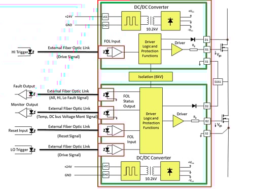
Figure 2. Basic schematic for the plug-and-play mSiC gate driver high-voltage module packages. This digital gate driver works out of the box and complies with major standards. Image used courtesy of Bodo’s Power Systems [PDF]
From Electrification to Grid Modernization
Wide bandgap SiC technology is already playing a key role in electrifying everything. It will soon tackle other major challenges, such as the need for a grid overhaul to achieve the necessary omnidirectional power flow to simplify how harvested energy gets through distribution to final conditioning and use.
These and other challenges will be easier to solve using a software-configurable SiC MOSFET gate driving approach. This approach reduces switching losses and ringing while improving system power density beyond what is possible using standard analog MOSFET gate drivers to mitigate SiC technology’s secondary effects. Developers have multiple build-or-buy options with mSiC gate drivers, from digital gate driver cores supported by module adapter boards to plug-and-play solutions that are pre-configured for widely adopted module packages—helping developers and designers adopt SiC with ease, speed, and confidence.
This article originally appeared in Bodo’s Power Systems [PDF] magazine.