 Facebook
 Google
 GitHub
 Linkedin
Q factor
Q Factor definition
The Q factor of a capacitor, also known as the quality factor, or simply Q, represents the efficiency of a given capacitor in terms of energy losses. It is defined as:
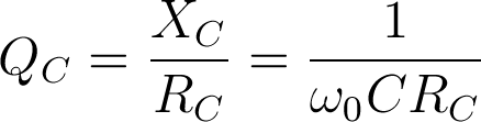
where QC is the quality factor, XC is the reactance of the capacitor, C the capacitance of the capacitor, RC is the equivalent series resistance (ESR) of the capacitor, and ω0 is the frequency in radians at which the measurement is taken.
In an AC system, the Q factor represents the ratio of energy stored in the capacitor to the energy dissipated as thermal losses in the equivalent series resistance. For example, a capacitor that is capable of storing 2000 joules of energy while wasting only 1 joule has a Q factor of 2000. Since Q is the measure of efficiency, an ideal capacitor would have an infinite value of Q meaning that no energy is lost at all in the process of storing energy. This is derived from the fact that the ESR of an ideal capacitor equals zero.
The Q factor is not a constant value. It changes significantly with frequency for two reasons. The first reason is the obvious ω0 term in the above equation. The second reason is that ESR is not a constant value with regard to frequency. The ESR varies with frequency due to the skin effect, as well as other effects related to the dielectric characteristics.
A related term, called the dissipation factor(DF), is sometimes defined in capacitor datasheets instead of the Q-factor. In AC circuits the DF is simply the reciprocal value of Q.
Why is the Q factor important?
Most applications do not have to take the Q factor into serious consideration, and standard capacitors may be used in those applications. However, the Q factor is one of the most important capacitor characteristics in the design of RF circuits. At RF frequencies, the ESR increases with frequency due to the skin effect. Along with the increase in ESR, dissipative losses increase as well. This is why RF circuits typically use high-Q capacitors to reduce high-frequency losses.
Typical appications that call for high-Q capacitors are RF matching applications, MRI imaging coils used in MRI scanners and other applications that have to be precisely tuned at higher frequencies. In some applications, the losses at the capacitor itself can be high enough to actually raise the temperature enough to de-solder from the board, which is why high-Q capacitors must be used in such applications. Even if the temperature increase isn’t as drastic, it can still affect the lifetime of other neighbouring components on the board. Another reason to use high-Q capacitors is the reduced thermal noise. All real capacitors have an equivalent series resistance, and this resistance creates additional thermal noise. In applications such as satellite receivers, noise levels are critical and high-Q capacitors are used in order to maintain the desired signal-to-noise ratio.
Typical values
Datasheets usually quote the Q factor at one or more frequencies. The standard frequency used in Q factor measurements is 1MHz. However, since the Q factor varies greatly with frequency, the Q factor given at 1MHz is not a good approximation of the Q factor at, for example, 2GHz.
Some datasheets will give Q factor values at higher frequencies if the capacitor was intended for use at high frequencies. Some datasheets will even provide a Q factor vs. frequency graph which can be used to deduce the Q factor at any given frequency.
Good high-Q capacitors can have a Q factor value of over 10,000 at 1MHz and over 1,000 at 100MHz, while standard capacitors can have a Q factor as low as 50 at 1kHz. The difference between a high-Q capacitor and a standard capacitor is in the actual design of the capacitor, as as well as the materials used. All connections and pins are kept as short as possible to reduce resistance, and are made from low-resistance materials such as copper. Most high-q capacitor manufacturers offer multilayer ceramic chip capacitors, which are small and sturdy, have a long lifetime, tight tolerances and great stability over time, providing high Q values, but are often limited to a few tenths of picofarads. Such capacitors can be used at frequencies of up to 20GHz, which is sufficient for most RF applications.
At lower frequencies, for example in audio applications, tantalum capacitors may be used as high-Q capacitors. They offer low ESR at sufficiently high frequencies and can sometimes be a viable alternative if higher capacitances (up to around 1mF) are needed by the circuit design.