Facebook
 Google
 GitHub
 Linkedin
Selecting the Proper Operation of Switching Power Transistors
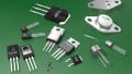
With 3 materials and about 8 types of transistors to select from — although not all combinations are available — the choice of the optimum switching transistor is difficult.
With 3 materials and about 8 types of transistors to select from - although not all combinations are available - the choice of the optimum switching transistor is difficult This article is especially also written for the benefit of our young engineers.
1. Requirements for Power Transistors
The same is not the same, the need for second sources. One is easily misguided by the assumption that transistors of the same type designation are indeed identical; nothing is further from the truth!
Each manufacturer has its own technology. In the semiconductor industry a product is introduced first by one company, if it is successful others will copy it and also the datasheet. They try to meet or exceed the specs of the original, but especially the switching behaviour is often different. As the copies are as a rule less expensive, the purchasing department will exert pressure on the designer to approve second source products. Indeed it is a designer's first priority to shun single-source products.
A single-source product not only prevents the purchasing dept from bargaining and force it to accept the seller's price, there is also a supply risk: the manufacturer may have production problems, or, worse, in times of high demand products can not just be bought, but are "allocated"; prices go up, delivery times may extend to years. If a product does not contribute enough revenue, it can be discontinued on short notice, maybe just in the moment, the designer's new circuit goes into production.
Hence the designer will have to test second-source products and modify his circuit so it will function also with those. In the BOM, the designer should approve at least two manufacturers.
If he enters just the type designation the purchasing dept will feel free to buy any product with that designation. This can lead to production halts or/and field failures
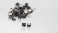
While it is easy to test TO-220 and TO-247 products SMD components have to be unsoldered and resoldered which can damage the parts or/and the board. TO-220's fit in sockets with 1/10th inch spacing, if a clip-on heat sink is used testing will be fast. A scope with at least 200 MHz bandwidth and a DC/AC current probe with at least 50 MHz will show voltage and current. It will be immediately obvious whether a transistor turns off slowly.
During turn-off the product voltage times current can assume high levels, if turn-off is too slow it can destroy the transistor. If the mathematics in the scope are used to calculate the instantaneous power it is necessary to first compensate for the time delay between voltage and current probes! In offline SMPS voltages as high as 800 Vp may occur so standard probes can not be used, only probes with at least a 1 KVp spec.
Even with tested and approved products, there is no certainty for the future. The semiconductor companies are continuously busy to shrink the chips or/ and change to a less expensive technology without changing the type designation. Sometimes an "A" will indicate a change. Do not expect that such an "A" type will be better, to the contrary, in most cases the part will be inferior to its predecessor. A smaller chip will be faster, but will take less overload, and its thermal resistance will be higher so it will run hotter. Seemingly "unexplainable" failures of new lots can be caused by such chip changes. The wise design engineer will always preserve some parts he used for the design so he can compare those with new lots.
The choice is difficult: there are 3 materials (Si, SiC, GaN) and the following types to select from: bipolar NPN and PNP, JFET, N- and P-channel, MOSFET, N- and P-channel, enhancement, depletion, standard and Coolmos (Superjunction). Not all conceivable combinations of materials and types are feasible resp. available, e.g. there are no JFET enhancement parts. While silicon and GaN allow power transistors on a chip together with other circuitry this is not possible with SiC. A major drawback of all new SiC and GaN parts is the lack of true second sources. If a supplier goes out of business as it has happened its customers will have to redesign.
2. Si Power Bipolars
Discrete Si bipolar power transistors are considered obsolete, most major firms discontinued production. However, they feature the smallest chips, simple processing, low cost and are still preferential for certain applications. Up to about 100 V they can be integrated with other circuitry. Whole families of such ic's are common and will remain: e.g. linear and switching voltage regulators. Linear regulators are low cost and feature excellent properties. With MOSFET pass elements the dropout voltages can be reduced to millivolts, but the chips are larger, the costs higher If the higher drop-out voltages of bipolar chips can be accepted, typically 1.5 V, their price/performance can not be beaten.
The so-called "low drop-out" bipolar regulators should be shunned. If no current limiting or short-circuit proofness are required, just any standard MOSFET and a TL 431 make up an excellent lowest drop-out and lowest cost regulator up to about 30 V; for higher output voltages a small cascode transistor can be inserted.
Bipolar transistors have low saturation voltages which rise little with increasing current, a great advantage over FET's, however, this requires high base currents. The problem of high base currents was solved by the IGBT with its MOSFET input. Bipolars were used in millions of tv sets as switching transistors in SMPS and the horizontal deflection circuits, but their base drive is very critical, especially during turn-off. High voltage bipolars suffer from low current gain. If they are allowed to saturate they will recover slowly.
If the maximum collector voltage is exceeded bipolars will break down. As long as the current is limited this first breakdown does not damage the part. As this breakdown is very fast, in the nanosecond region, high amplitude short pulses used to be generated this way.
There are important descendants of bipolars: thyristors, triacs which are hard to beat because they are reliable low-cost components.
In the 1960's the second-breakdown was discovered which affects bipolars from 16 V on. By no means any combination of collector voltage and current is allowed; the higher the voltage the lower the permissible current. The maximum power dissipation specified is only available below appr. 16 V. For each type of transistor a so-called SOAR = safe operating area is given in the datasheet: a set of curves in the collector voltage vs. collector current diagram with the time as the parameter. Note that this is valid only for Tj = 25 C and has to be derated beyond.
The electric fields are such that the current concentrates in hot spots where the silicon melts so a short develops. The worst case is dc resp. continuous operation: even big transistors sustain only very small currents at high voltages. Fast switching is mandatory for survival.
Common bipolar power transistors are fairly slow. In order to raise tT multi-cell transistors were designed with fT's of several hundred MHz; the smaller types reached several GHz. In fact, e.g. high-quality audio amplifiers require at least an ft of 100 MHz. At the same time, such multi-cell transistors are less prone to second breakdown.
3. Standard Si MOSFET Power Transistors
3.1 Structure
The first power MOSFETs - which differ from small signal MOSFETs - came around 1978 on the market, a major supplier was Siliconix. They were so-called V-MOS devices. A MOSFET is characterized by a subsurface channel between source and drain, a SiO2 insulation layer with the gate electrode on top. The gate is hence isolated so there is no static gate current. With sufficient gate voltage, a conductive channel is formed through which the current can flow in both directions.
This channel has a resistance, the Rdson, with the disadvantage that the losses increase with the square of the current. Most MOSFETs are N-channel enhancement types, i.e. normally off and require about 12 V of gate drive which is easily delivered by standard ic's. The minimum threshold voltages are between 1 and 4 V. P-channel enhancement MOSFETs up to 500 V are available, in the low power family also depletion types. Depletion MOSFETs are unfit for use in SMPS because they are fully on with zero gate voltage; at turn-on of the power supply they will hence present a short.
With regard to the leakage current, the impedance at the gate must stay sufficiently low in order to prevent parasitic turn-on. Note that all drivers require a minimum supply voltage for proper function, below this the output to the MOSFET remains high impedance; therefore a resistor of typically < 100 K is required to prevent parasitic turn-on which may be destructive.
As described later, during turn-off, a sizeable capacitive current can come out of the gate which can cause parasitic turn-on unless the gate circuit is sufficiently low impedance. Seemingly "unexplainable" failures can have their cause here. Maximum gate voltages are typically +- 20 V so there is ample reserve. There are also low threshold devices compatible with logic families. By doping or ion implantation, any desired threshold voltage can be achieved.
Power MOSFETs have large input, reverse and output capacitances which can exceed 10 nF, hence sizeable peak currents are necessary for fast switching. It s important to note that during switching from off to on and in reverse a transistor will traverse its linear region. Strong Miller effect increases the input capacitance so much that the gate voltage will show a plateau until the Miller effect disappears again in the on resp. off state. This effect slows the switching and can only be overcome by high peak current drivers or in the cascode circuit.
Today's MOSFETs differ substantially from those first ones. The breakthrough came when several large companies brought multi-cellular chips on the market; IR called them Hexfets because the cells were hexagonal. Motorola called them TMOS, Siemens SIPMOS etc. By paralleling thousands of such cells high voltages and currents were realized while at the same time the Rdson's remained low. Fig. 3.1 shows the structure of Siemens/Infineon MOSFETs.

Figure 3.1: Structure of early Siemens/Infineon power MOSFETs, all other companies have similar structures. The MOSFETs consist of ten thousands of parallel-connected cells, the drain is at the bottom. The structure is very similar to an integrated circuit and derived from multicellular power bipolars.
The true internal structure of power MOSFETs was first disclosed by Harris Semiconductor in two AppNotes. Figure 3.2 shows it is a cascode, the power device is a JFET, the lower transistor in the cascode is a MOSFET. The internal node of the cascode is not accessible, the same as in an IGBT. As a consequence one can only influence turn-on, but not turn-off! One can turn the MOSFET at the gate quickly off, but how the device turns off can not further be influenced from the gate. Typically, the current quickly falls to about half, then remains at that level for some time before falling to zero. While the drain voltage rises fast the product voltage times current increases; if the turn-off lasts too long, excessive losses will be incurred which can cause destruction. Mosfets of the same type designation may differ very substantially in their switching behaviour, good ones will switch off fast, others may take more than 100 ns.

Figure 3.2: True internal structure of power MOSFETs of the 2nd generation. It is a cascode, and the power device is not a MOSFET, but a JFET! The lower transistor is a MOSFET. The parasitic NPN across the output is obvious, its base is short-circuited by aluminum; in the lower simplified equivalent circuit, it is not contained. The circuit in the middle is fairly complete; the 3 capacitances shown are given in the datasheets.
The picture explains that during turn-off current continues to flow through the capacitances between drain and gate and out of the gate. The driver must be able to accept this current. This is also one reason why the external gate resistor must be paralleled by a fast diode in order to prevent that this current builds up too high a voltage across the resistor. For medium-sized MOSFETs, a 1 N 4150 does the job.
Currents from the gate can try to pull the driver's output below ground or beyond Vcc which can cause malfunction or destruction of driver ic's. Hence it is mostly necessary to connect a 1 A power Schottky diode from the output to ground and also from the output to Vcc. If the driver’s impedance is too high, the current coming out of the MOSFET can develop a voltage high enough to turn it back on, parasitic turn-on, which causes additional losses or even destruction. This problem also affects SiC MOSFETs.
The standard power MOSFET is available up to 800 V, there are a few 1000 V types, some Japanese manufacturers offer 1700 V, but those suffer from the drawback that the chip size increases with the voltage. Apart from the high cost of large chips their capacitances also become excessive.
3.2 Second Breakdown
Another problem is the existence of a parasitic NPN bipolar transistor in parallel to the output. Manufacturers touted that MOSFETs were free from second-breakdown. This was quickly proven wrong, the cause being the parasitic NPN. Second breakdown is known from bipolars. Although its base is short-circuited by aluminum a high dv/dt on the output = drain = collector will create such a high current through the collector-base capacitance that enough voltage is developed across the base-emitter junction to turn it on which will immediately destroy the transistor. Mosfets' data sheets hence contain SOAR characteristics which show the permissible current vs. the drain-to-.source voltage with the time as the parameter.
The problem lies in imperfect uniformity of the many thousand cells. The threshold voltage has a negative TC; if a cell is a bit hotter than its neighbours it will attract current from them which creates a hot spot. If the temperature exceeds the 150 or 175 degrees C a short will develop. Uniformity has been so much improved that (Si) MOSFETs carry an avalanche rating which has to be observed in addition to the SOAR ratings. Watch especially the region about the maximum Vds and low currents which is critical with regard to SB.
Note that all these characteristics pertain to 25 C and have to be derated for the actual working Tj. Mostly two avalanche ratings are specified: a higher rating for a single pulse and a periodic rating. Single-pulse ratings are of doubtful value because in case of failure it can never be proven whether the pulse which caused destruction was within the rating
Figure 3.3 shows the results of the tests. A 400 V MOSFET, when stressed with 100 % power dissipation, failed already at 45 V. Even an 800 V MOSFET failed already at little more. Even if they are only stressed with 50 % power dissipation both are destroyed at 100 V. Only after these results were presented to the manufacturers they admitted the truth, and since then there are SOAR characteristics in the datasheets.

Figure 3.3: Test results taken on standard power MOSFETs prove that they suffer from second-breakdown. The danger of destruction increases with dv/dt.
This avalanche-proofness is one of the most important advantages of Si MOSFETs, sofar unmatched by SiC and GaN, both lack avalanche ratings, GaN is destroyed by a single overvoltage pulse. SiC manufacturers announced they would soon specify avalanche ratings; due to the similarity between Si and SiC MOSFETs it is not unlikely that they will succeed.
The symbol is often shown with a Zener in parallel to the drain-source terminals. During avalanching, a modern MOSFET can dissipate a lot, but it is not advisable to let a part avalanche continuously, but only in overload situations like turn-on. Avalanching is a stochastic process which generates EMI.
3.3 Rdson, Switching Losses
Standard Si MOSFETs suffer from an exponential increase of the Rdson as a function of the breakdown voltage as shown in Figure 3.4.

Figure 3.4: Contributions to the Rdson of standard Si power MOSFETs.
Figure 3.4 shows a table of the percent contributions to the total Rdson from 30 to 600 V. The high percentage of the epi layer is evident; its contribution depends on the doping level and its thickness. A meaningful reduction of total Rdson depends hence on these parameters, but higher doping and a reduction of thickness will reduce the breakdown voltage, so this is the reason for the strong dependence of Rdson on the voltage.
Rdson is often overestimated, in actual switching operation at frequencies > 100 KHz the switching losses are predominant. The quest for low Rdson entails higher capacitances which slow the switching down, thus generating higher losses. Faster switching requires either a powerful driver or a cascode; The latter is the best and most cost-effective solution, still not as well known as it should. Many SiC and GaN manufacturers offer their JFETs in cascodes which, however, makes only sense in bridge circuits. In a cascode the lower transistor, a standard lv MOSFET, determines the performance, the upper transistor can be almost any.
For single switches a Coolmos is best upstairs, SiC or GaN offer no advantages here, to the contrary, they are not avalanche-proof. Funny enough, the manufacturers of Coolmos MOSFETs have not yet offered cascodes. From the above, it follows that there is always an optimum MOSFET for each application with the perfect combination of Rdson and capacitances. Datasheets offer only a rough guide for the selection of a transistor!
State-of-the-art MOSFETs have become ever better: lower Rdson and lower capacitances, but also the chips became smaller. The thermal resistance of recent chips is hence much higher than that of older ones, also the thermal capacitance is lower. In case of overload e.g. these chips become hotter and fail sooner than their predecessors.
Standard MOSFETs remain in the lv field where Rdson's below 1 mOhm were realized. In the HV field Coolmos has replaced them. Hv standard MOSFETs are still necessary e.g. for linear voltage regulators. A MOSFET and a TL 431 make up an excellent voltage regulator, for higher voltages than about 30 V, a cascode HV transistor can be inserted between MOSFET and TL 431.
4. Si Coolmos (Superjunction) Transistors
The road to highly efficient high voltage switches was hitherto blocked by the so-called "silicon limit": the V2.4 ... 2.6 relationship between the Rdson and the blocking voltage. In MOSFETs, the current flows vertically through the voltage-sustaining layer to the backside drain contact. The doping of this layer has to stay low. The IGBT has lower losses because it profits from two charge carriers but it suffers from high turn-off losses and is confined to low-frequency operation. What is needed is a switch with zero charge carriers in the off-state and plenty in the on-state.
Siemens (Infineon) succeeded around 1998 in realizing a revolutionary new HV switch, called "Coolmos", other companies use the name "Superjunction". By this invention, it is possible to have high voltage MOSFETs with low Rdson's, because the Rdson does not rise exponentially but only linearly with voltage. In the meantime, many generations of Coolmos appeared.
Coolmos is based on the so-called compensation or resurf principle, see Figure 4.1. Hundred thousands of p columns reach into the n zone, in the off-state the net charges compensate one another. In the on-state, one of the two carriers can be highly doped. The problem was to find a way to manufacture the column structure while maintaining the balanced charges. Figure 4.2 shows the production process.

Figure 4.1: From the resurf principle to Coolmos.
The challenge was to find a production process which allowed to fabricate the densely packed deep p - columns while preserving and controlling the charges of the p- and n- columns. Infineon uses the so-called multi-epitaxial method. Starting with an n+ - substrate first a layer of n- - material is deposited. Through a mask, boron is implanted. Then the next layer follows until kind of a cake is grown. Then columns are formed by diffusion. This process is considerably more complex and expensive than the standard MOSFET process.

Figure 4.2: Infineon Coolmos production process
The most important advantage of the Coolmos process is the replacement of the V2.4 ... 2.6 dependence of the Rdson on the voltage by a linear one. This was achieved by separating the p- and n - columns within the cells. Coolmos chips are much smaller than standard MOSFET ones of identical Rdson and voltage, also the capacitances are lower, but Rth is increased.
At turn-on, the field in the Coolmos immediately collapses. This is not only caused by the channel current, but also by the holes drift current from the p-columns which is a specialty of the compensation principle. This is one reason why the switching losses are lower than those of standard MOSFETs.
If a turn-off voltage is applied, see Figure 6.1 right and Figure 4.3 right, the charge carriers along the circumference of the PN- zone are first pushed out; a space charge zone is created alongside the columns which generates a lateral field component. At the same time the charge carriers are forced out of the drift zone into the p- and n - columns. Already at < 50 V the columns structure is fully depleted, and the space charge zone functions like a quasi - intrinsic layer. With rising blocking voltage, after depletion of the column structure, the vertical field in the space charge zone increases which reaches farther into the rest of the drift zone. Eventually, a field distribution results with overlapping vertical and horizontal components. In order to achieve a minimum Rdson and a maximum blocking voltage, both components should be equal.

Figure 4.3: Coolmos conducting and blocking.
Figure 4.4 shows the actual switching behaviour of standard and Coolmos MOSFETs. Note that at turn-off the current first falls to about half, to a pedestal of some length, before the current falls to zero. The product of current times voltage increases fast, if the pedestal lasts too long - with poor transistors beyond 100 ns - it can destroy the part. Note that the time delay between current and voltage probes must first be compensated, otherwise the calculated product will be in error.

Figure 4.4: Switching behaviour of standard and Coolmos MOSFETs.
The question whether there is a limit to the compensation principle is answered by pointing out the process difficulties which can eventually not be mastered. It is possible to reduce the distances between the P and N - regions and to increase the doping levels such that the Rdson is reduced while the blocking voltage remains the same, however, the lithography and the precision of the doping set the limits.
As described in chapter 3, also in Coolmos the power transistor proper is a vertical JFET, consisting of the p - zone column structure. In case of excess current or short-circuit, the JFET is pinched off by the rising voltage alongside its structure. Current limiting occurs sooner than with standard MOSFETs. The short-circuit current remains approximately constant within the SOAR.
An interesting alternative production process is the so-called "deep trench filling". The multi-epitaxial process described above is expensive and complicated, any further reduction of the Rdson requires more process steps. Some companies developed the "deep trench filling" method. This process consists only of two steps: First deep trenches are formed, then p-material is epitaxially grown. This eliminates a large number of formerly required steps. At the same time finer and more sharply defined structures become possible allowing lower Rdson and gate charge. The company claims to have the lowest specific Rdson in the 600 V class and the lowest Rdson in any case.
Coolmos quickly replaced the standard MOSFETs at higher voltages, however, they are markedly more expensive. Today, there are several families of Coolmos, optimized for specific applications. The newer chips are very fast and switch offline voltages in < 20 ns if properly driven, in a cascode < 5 ns, rivalling GaN and SiC while preserving avalanche-proofness which both can not offer. Reminder: too fast switching has also undesirable consequences: stronger EMI and higher dielectric stresses on all insulation materials. Note the dv/dt specs, excessive dv/dt risks destruction.
Figure 4.5 shows the gain in Rdson for early Coolmos.

Figure 4.5: Rdson improvement by Coolmos. The picture shows the Rdson gain of an early Coolmos (SIP 5). Both chip areas are equal. For MOSFETs of 1 KV, the gain is tenfold.
Regarding Rdson: Infineon offers since many years a 19 mOhm/600 V Coolmos. The claims of GaN manufacturers of Rdson's "many orders of magnitude lower than silicon" were ridiculed as they could not even beat this Coolmos part. SiC MOSFETs with lower Rdson appeared only recently.
It should be stressed again that the Coolmos chips are much smaller than those of comparable standard MOSFETs', so their thermal resistances are higher and their thermal capacitances lower. They can not take as much overload and run hotter for the same power dissipation. It is, therefore, good practice to choose a part one or two sizes larger than the data sheets imply. While e.g. the Rth's of older chips in TO220 are between 0.5 and 1 degree C/W, newer chips are between 1 and 2 degrees C/W. A frequent misconception is to mix up maximum operation Tj and life. the max op Tj only says that the part will operate up to that Tj, but not how long! The iron rule "life is halved for each 9 K temperature increase" remains valid! The "maximum dissipation" is mostly given for operating conditions which can never be realized, e.g. Tc = 25 C. The avalanche - proofness of Coolmos is also lower than that of standard MOSFETs, again due to the smaller chips.
There are 3 voltage ranges: 500 V, 600 (650) and 800 (900) V. For offline flybacks a higher spec than 650 V is not necessary. Parts with faster body diodes i.e. better reverse recovery are available.
Coolmos capacitances are lower at high drain voltages but markedly higher at low voltages as shown in Figure 4.6. Coolmos output capacitance is highly nonlinear which causes a "tail" during switching.

Figure 4.6: Comparison of the output capacitances and Rdson's of standard and Coolmos MOSFETs.
Samsung invented two-chip parts in standard housings which contain a standard MOSFET and a bipolar driver chip on a common lead frame. Infineon copied this, using their Coolmos chips and created extremely efficient solutions for low power SMPS.
About the Author
Dr.-Ing. Artur Seibt is a professional electronics design lab consultant with specialization in SMPS with 40 yrs. experience incl. SiC, GaN, D amplifiers. Inventor of current-mode control (US Patent) and He is also an expert in EMI design.
This article originally appeared in the Bodo’s Power Systems magazine.