Facebook
 Google
 GitHub
 Linkedin
Pulsed Field Magnetometry for Characterization of Magnetic Components
This article describes the BsT-Pulse software and its algorithm, allowing an evaluation of high power magnetic components and is easily expandable, due to its modular structure.
Driven by the soaring demand for hybrid and electric vehicles and the large investments in renewable energies, the soft magnetic materials market is expected to reach the €100 billion mark by 2026. Together with an increasing number of stringent regulations (particularly in EU) also in developing countries like China, this growth is expected to drive the emergence of advanced material and component equipment for the automotive, infrastructure,and semiconductor industries.
It is therefore essential to select accurate and reliable testing equipment and to develop efficient materials for key grid components and thus limit power loss and maximize system efficiency. However, there is still a clear lack of accurate measuring systems to test nonlinear high power, high current magnetic components in DC voltage grids, which leads to pressing market demands for innovative advanced quality testing solutions for innovative, especially low permeable magnetic materials.
The Thyristor based technology enables bipolar excitation on the Device Under Test (DUT), the transient large amplitude of current in conjunction of voltage decay enables direct illustration of correlations of amplitude inductance and (re)magnetization current, accurate di/dt sensor technology enables additionally the differential inductance, which is corresponding to incremental permeability of materials and responsible for loss behavior in the region around saturation.
Measuring principle
An equivalent circuit of the measuring system is illustrated in Figure 0 [0]
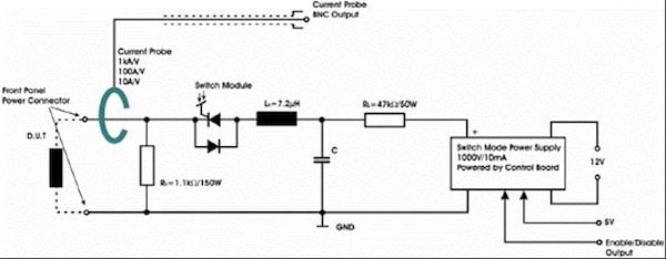
Figure 0: Basic circuit layout of the pulse generator.
Measurement begins with the charging of the capacitor to a specified voltage, which is corresponding to those under real application conditions for the DUT. When the voltage level is reached, the known capacitor and the nonlinear DUT are forming a series of RLC circuits. As long as the inductance is performed in a linear area, a second-order differential equation can be derived with fixed resonance frequency [1]. However, the charged pulse energy applied to the DUT can drive it into saturation. Due to an integrated free-wheeling diode, the resulting discharge circuit is capable of full current reversal. Hence, a degaussing transition will be created which can be monitored by current and voltage probes in order to illustrate the saturation behavior of the DUT.
Development of software
To characterize the properties of magnetic components, which are tested with the BsT-Pulse device, software has been developed. This software allows the control of the device to trigger the pulse process itself. In most evaluation cases it is of utmost interest to drive the tested component into saturation. Since the saturation characteristics is dependent on the magnetization current amplitude, a decisive factor for a test is the charged pulse energy (know parameter) with the desired voltage pulse level, which represents dB/dt, magnetization rate. Therefore, the charging voltage of the capacitor can be directly adjusted via the user interface, whereby the maximum value of a single module is 1000 V.
The software for the BsT-Pulse device also includes data acquisition. When a pulse process is triggered the capacitor is charged up to the preset voltage level and then discharged via the connected DUT, resulting in a damped resonant circuit. If the voltage pulse level is sufficiently high, the DUT alternately transitions into saturation and desaturation. During these transitions, the instantaneous voltage and current curves at the DUT are acquired. The voltage and current decay form the basis for all evaluations in the software. Furthermore, this raw data set can be saved for every pulse test, allowing the user to perform own evaluations and further data processing.
A) Inductance analysis
The data evaluation in the BsT-Pulse software essentially provides inductance analysis, energy loss calculation and the characterization of material properties such as permeability and magnetic field.
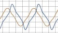
The inductance of the tested component is calculated depending on the instantaneous current amplitude. In addition, since there will be multiple transitions between saturation and desaturation, an algorithm is used to automatically detect and evaluate all magnetization periods from zero to maximum current (“rising half periods”). The following figure shows an exemplary voltage and current decay measurement.
The detection of the periods, for which the inductance is calculated, is basically divided in two steps. First, the extrema of the current signal are determined. Considering that the voltage drop at the DUT includes an inductive and resistive part, these extreme values can thus be used to predict the resistance of the connected DUT. Since the derivative of the current signal is zero at these extreme values, the inductive part of the voltage drop at the corresponding points
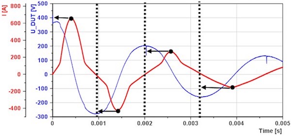
Figure 1: Detection of magnetization periods
is also zero. This way, it is possible to calculate the resistance by simply dividing the measured DUT voltage and current at these very points. Continuing with the detection of the magnetization periods, the current-zero points left of the extrema then mark the beginning of the associated magnetization periods. Therefore, the inductance analysis results in an array of inductance curves, which is illustrated in the next figure (one curve for each magnetization period).
In addition to that, the software includes different methods for the inductance analysis. On the one hand, the differential inductance is calculated, which for example allows the determination of the saturation current. On the other hand, the software calculates the amplitude and energy equivalent inductance curves. Especially the energy equivalent inductance is useful in converters, such as inverting choppers, flyback converters, and Cuk converters, which first store energy in an inductive component and deliver it to the load. [2] It is as well useful to formulate the Q factor of DUT at large current amplitude. The next figure shows a direct comparison between the three inductance evaluations within the same measurement period.
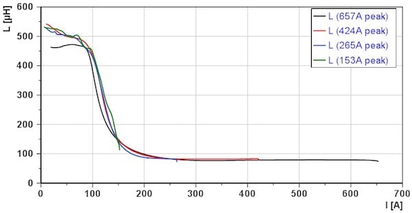
Figure 2: Array of inductance curves
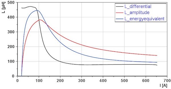
Figure 3: Differential, amplitude and energy-equivalent inductance
In particular, the calculation of the differential inductance is a challenge, which is due to the limited resolution of the A/D converter of the oscilloscope. Two approaches have been developed to handle this problem. The first approach is to use a precise current monitor to directly measure the impulse current and then apply signal conditioning in the form of two smoothing-filters. The first filter is a weighted moving average to reduce the quantization noise in the current signal, whereas a second Savitzky-Golay filter is used as a standard tool for smoothing. The second approach is to acquire the current increase rate directly via the voltage drop across the air coil (discharge limiting inductor of thyristor). The air coil voltage can be considered as a reference measurement. This approach allows evaluating the differential inductance without actually calculating the derivative of the current signal.
B) Loss analysis
The second part of the BsT-Pulse software is the evaluation of energy loss. For this purpose, the software automatically detects two peaks in the voltage signal of the DUT and calculates the insertion loss in dB as well as the energy loss in Joule for the area between the two peaks. Furthermore, the user has the possibility to choose a custom area for the loss evaluation.
Additionally, the inductor quality factor can be derived, using the ratio between the reactance (energy equivalent inductance) and resistance of the DUT. [1] The phase angle between voltage and current is not affecting the results. [3] This is especially advantageous for metal alloyed powder material with a phase angle close to 90°.
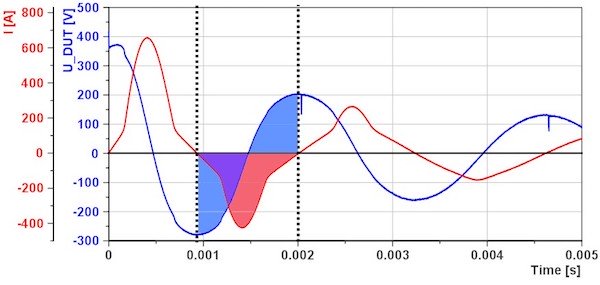
Figure 4: Energy loss evaluation
C) Material characterization
The material properties of the DUT can also be evaluated by entering the relevant parameters of the DUT. Those are the effective length and area of the magnetic circuit, the geometry of core shape, and the number of windings, coil design. Given these parameters, the software is able to calculate the curves for permeability, magnetic field strength as well as magnetic flux density. The following figure shows the calculated permeability and magnetic flux density depending on the magnetic field strength for a DUT as a measurement example.
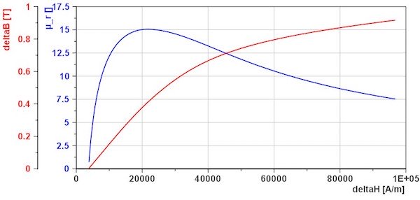
Figure 5: Material properties evaluation
As far as possible the software will use the second detected magnetization-period to determine the material properties. This way the potential uncertainty of remanence effects can be eliminated, regardless of opened or closed magnetic path of the DUT.
As mentioned before, the raw data (voltage and current signals) may be used for further offline evaluations. In case of the H1016 DUT*, the measured data, for example, was used to calculate the material properties over the whole measurement range. This allows visualization of all saturation-desaturation transitions in the form of a (re)magnetization curve, as shown in the next figure.
*DUT is inductor, number of windings is 53 (flat edge wire), manufactured by company, there are two metal alloyed powdered cores stacked, by CSC (PDF).
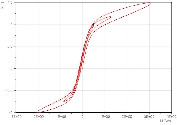
Figure 6: Example for offline evaluation: (re)magnetization curve
Summary
BsT-Pulse, a safe, compact and robust product that ensures a reliable and reproducible pulse measurement is the new generation pulse device, to characterize the high power magnetic component, enables the specification with the limit value.
The BsT-Pulse software and its algorithm are described, and it allows an evaluation of high power magnetic components and is easily expandable, due to its modular structure. Depending on requirements, additional features such as inductance threshold monitoring or detection of coil insulation faults can be implemented in order to extend the evaluation part of the software. With regard to convenient data scanning and storage, it is likewise conceivable to use barcodes in order to represent the data of magnetic components or to use databases instead of classical measurement data models.
About the Author
JC Sun is the founder of Bs&T Frankfurt am Main GmbH, a company located in the north of the metropolis Frankfurt am Main and specializes in the development and manufacture of integrated hyster loop measuring systems. He worked for two decades as a development engineer in power electronics; developing various soft magnetic materials and was a project manager for various companies.
B. Zumeri worked for MS+D GmbH (msplusd.de) , a company that have been developing solutions for new fields of work from all areas of technical computer science.
This article originally appeared in the Bodo’s Power Systems magazine.