Facebook
 Google
 GitHub
 Linkedin
Megohmmeters and Insulation Tester Applications and Measurement Procedures
Learn how to properly utilize megohmmeters and insulation testers.
A megohmmeter is a high-resistance ohmmeter used to measure insulation deterioration on various wires by measuring high resistance values during high voltage test conditions. Megohmmeter test voltages range from 50 V to 5000 V. A megohmmeter detects insulation failure caused by excessive moisture, dirt, heat, corrosive substances, vibration, and aging (See Figure 1). Megohmmeters are sometimes referred to as insulation testers.

Figure 1. Megohmmeters are available in different designs with a variety of functions and features. Image courtesy of Global Test Supply
Megohmmeter Applications
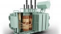
Some insulation, such as that found on conductors used to wire branch circuits, is thick insulation that is hard to damage or break down. Other insulation, such as the insulation used on motor windings, is very thin (to save weight and space) and breaks down more easily. Megohmmeters are used to test for insulation breakdown in long wire runs, motor windings, and transformers (see Figure 2).

Figure 2. Megohmmeters measure insulation deterioration on conductors, motor windings, and transformers. Image courtesy of Ubuy
The minimum resistance of motor windings depends on the voltage rating of the motor. The minimum acceptable resistance measurements are typically found in manufacturer-recommended resistance tables (see Table 1).
|
Motor Voltage Rating (From Nameplate) |
Minimum Acceptable Resistance |
|
Less than 208 |
100,000 Ω |
|
208-240 |
200,000 Ω |
|
240-600 |
300,000 Ω |
|
600-1000 |
1 MΩ |
|
1000-2400 |
2 MΩ |
|
2400-5000 |
3 MΩ |
Table 1. The minimum resistance of motor windings depends on the voltage rating of the motor as recommended by the manufacturer.
Insulation allows conductors to stay separated from each other and from the earth’s ground. Insulation must have a high resistance to prevent current from leaking through the insulation. All insulation has a finite resistance value that allows some current leakage to occur. Leakage current is current that leaves the normal path of current flow (hot to neutral) and flows through a ground wire. Under normal operating conditions, the amount of leakage current is so small — measured in microamperes — that the leaking current has no effect on the operation or safety of a circuit. The total leakage current through insulation is the combination of conductive leakage current, capacitive leakage current, and surface leakage current.
Conductive Leakage Current
Conductive leakage current is the small amount of current that normally flows through the insulation of a conductor. Conductive leakage current flows from conductor to conductor or from a hot conductor to the ground. Ohm’s law is used to determine the amount of conductive leakage current.
Insulation decreases in resistance as insulation ages and is exposed to damaging elements. The resistance of conductor insulation decreases as conductive leakage current increases. An increase in conductive leakage current results in additional insulation deterioration. Conductive leakage current is kept to a minimum by keeping insulation clean and dry.
Capacitive Leakage Current
Capacitive leakage current is leakage current that flows through conductor insulation due to a capacitive effect. A capacitor is an electronic device used to store an electric charge. A capacitor is created by separating two plates with a dielectric material. Two conductors that run next to each other act as a small capacitor. The insulation between the conductors is the dielectric, and the conductors are the plates.
Conductors carrying DC voltages typically produce little capacitive leakage current because the capacitive leakage current lasts for an extremely short time period and then stops. AC voltages produce continuous capacitive leakage current, but the capacitive leakage current can be kept to a minimum by separating or twisting the conductors along the run.
Technical Tip
According to the International Electrotechnical Commission Safety Standard 950, double-insulated meters can have a maximum leakage current of 0.25 mA, and grounded handheld meters can have a maximum leakage current of 0.75 mA.
Surface Leakage Current
Surface leakage current flows from areas on conductors where insulation has been removed to permit electrical connections. Conductors are terminated with wire nuts, splices, push-on connectors, terminal posts, and other fastening devices at different points along an electrical circuit. The point at which insulation is removed from a wire provides a low resistance path for surface leakage current, with dirt and moisture allowing additional surface leakage current to occur. Surface leakage current results in increased heat at the point of connection. Increased heat contributes to an increase in insulation deterioration, which makes the conductor brittle. Surface leakage current is kept to a minimum by making all connections clean and tight.
With conductors carrying AC voltage, surface leakage current flows continuously as AC voltage alternates.
Megohmmeter Measurement Procedures
Megohmmeters send high voltages into conductors or motor windings to test the insulation (see Figure 3). Before taking any resistance measurements using a megohmmeter, ensure the meter is designed to take measurements on the circuit being tested. For all measuring precautions, restrictions, and procedures, consult the test instrument's operating manual. Always wear required personal protective equipment and follow all safety rules when taking the measurement. To take a resistance measurement with a megohmmeter, apply the following procedures:
1. Ensure that all power is OFF in the circuit or component being tested. Test the circuit for voltage using a voltmeter.
2. Set the megohmmeter function switch to voltage (the proper voltage range for the circuit to be tested).
3. Plug the black test lead into the negative (earth) jack.
4. Plug the red test lead into the positive (line) jack.
5. Ensure that the batteries are in good condition. A megohmmeter does not contain batteries if the meter includes a hand crank or if the meter plugs into a standard 115 V receptacle.
6. Connect the line test lead (red) to the conductor being tested.
7. Connect the earth test lead (black) to the second conductor in the circuit or to the earth ground.
8. Press the test button or turn the hand crank on the megohmmeter and read the resistance displayed (can take 10 secs to 20 secs). Change the megohmmeter resistance or voltage range if necessary.
9. Consult the equipment manufacturer or megohmmeter manufacturer for the minimum recommended resistance values. The insulation is in good condition when the megohmmeter reading is equal to or higher than the minimum values indicated by the manufacturer.
10. Remove the megohmmeter from the conductors.
11. Discharge circuit or conductors being tested.
12. Turn the megohmmeter OFF.

Figure 3. Megohmmeters send extremely high voltages (50 V to 5000 V) into wires or motor windings during testing. Image courtesy of Instrumart
Important Note
Verify that voltage is not present in a circuit or component being tested before taking any resistance measurements with a megohmmeter. Ensure that no part contacts the high-voltage section of the megohmmeter test leads.