 Facebook
 Google
 GitHub
 Linkedin
Alternating Current (AC) Load Control with Triacs
Read on to learn how a triac along with phase-control circuitry can be used to control the current that flows through an AC load.
The average load power is controlled by varying the RMS value of the load voltage. This may be achieved by using inverse parallel-connected SCRs, or by using a single triac.
Alternating current load control using triacs is the most common thyristor control method for low to moderately high power AC loads. The load power is controlled by controlling the RMS value of the load voltage, which in turn is controlled by the trigger angle of the triac. This, in turn, controls the conduction time of the triac.
When the trigger angle α is zero, the conduction angle θ will be 180°, and the load voltage will be a maximum and equal to the supply voltage. As the trigger angle is increased, the conduction angle will decrease, and the load voltage will decrease. When α is equal to 180°, θ will be zero, and the load voltage will be zero.
The trigger circuit most commonly used with a triac to control AC loads is the diac trigger circuit shown in Figure 1.
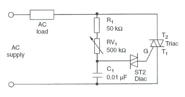
Figure 1. Triac control of AC loads.
The trigger angle is controlled by varying the setting on the potentiometer RV1. As this value is increased, the time taken for the capacitor to charge up to the break-over voltage of the diac will increase. This will delay the trigger angle and therefore reduce the conduction time. This, in turn, causes the load voltage to be reduced.
With the circuit arrangement above, the load may be controlled from full conduction through to almost zero. However, when the load voltage is increased again, a ‘snap-on’ effect is noticed. This is caused by a residual charge on the capacitor. The snap-on is evident because the current will suddenly increase from zero to some intermediate value.
The snap-on effect may be reduced by one of two methods:
· using an asymmetric diac (ST4)
· introducing a second time delay in the trigger circuit, as shown in Figure 2.

Figure 2. Triac control of AC loads with reduced snap-on effect.
In both circuits (Figures 1 and 2), the trigger circuits are not suited to extra-low voltage supplies. This is due to the relatively high break-over voltage of the diac, which is normally in the range of 28 to 36 V.
For example, if a diac has a break-over voltage of 30 V and is operating in a circuit connected to a 32 V supply, it will not be possible to trigger the diac until 41° into the cycle. The range of control is therefore very restricted. By contrast, if the supply is 240 V, the minimum trigger angle is 5°.
This problem may be overcome by using either a UJT or a PUT trigger circuit. With both circuits, the trigger angle may be controlled from almost 0° to 180°. A representative UJT circuit is shown in Figure 3.
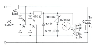
Figure 3. Triac load control—UJT triggering.
Important points that should be noted for the UJT trigger circuit are:
· The trigger circuit is connected in such a way that it will be turned off when the triac is triggered. There will therefore be only one trigger pulse in each half-cycle.
· Trigger pulses of one polarity only are available.
· The pulse transformer is connected in such a way that the triac will be triggered in modes 2 and 3, maximizing triggering sensitivity.
In terms of the output voltage and output voltage waveform, the only difference between the two circuits is that the UJT trigger circuit will provide a wider range of control when operating from an extra-low voltage supply. It is not normal practice to use the diac trigger circuit when operating from an extra-low voltage supply.
Output Voltage
The load voltage may be determined from a circuit characteristic. The actual calculation of load voltage is complex and will not be discussed in this article. The circuit characteristic is shown in Figure 4.
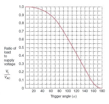
Figure 4. Alternating current controller circuit characteristics.
To obtain the load voltage for a particular trigger angle, project up from the horizontal axis at the appropriate trigger angle until the curve is intersected. Then project horizontally across to the vertical axis to obtain the ratio of load to supply voltages. The ratio is multiplied by the supply voltage to give the load voltage.
Example
A triac is used to control the power in an AC load with a supply voltage of 240 V. Determine, using the circuit characteristic, the load voltage when the trigger angle is set to (a) 20° (b) 60° (c) 120°.
From the circuit characteristic, the ratio VL/VAC is equal to:
(a) When α = 20° (circuit char. = 0.98):
VL=0.98*240 = 235.2 V
(b) When α = 60° (circuit char. = 0.88):
VL=0.88*240 = 211.2 V
(c) When α = 120° (circuit char. = 0.44):
VL=0.44*240 = 105.6 V
Waveforms
The waveforms produced by a triac controlling a resistive AC load for a trigger angle of 45° with diac triggering, and 90° with UJT triggering, are shown in Figures 5 and 6, respectively.
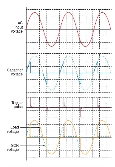
Figure 5. Triac AC load controller—diac triggering (trigger angle 45°).
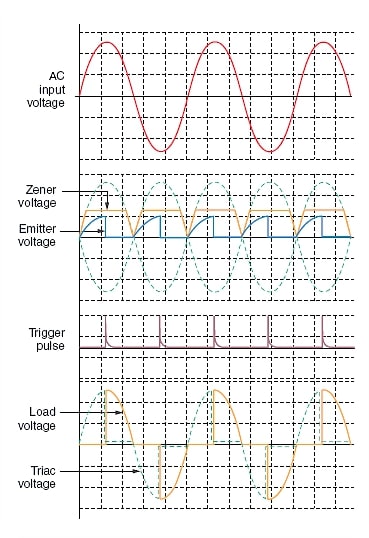
Figure 6. Triac AC load controller—UJT triggering (trigger angle 90°).
The triac controller is used to control low to moderately high power loads. Some examples are:
· lamp illumination
· fan speed control (ceiling fans)
· motor speed control (limited to small motors)
· heating elements in cooking and heating appliances.
For higher current requirements, available triacs may not be capable of carrying the required load current. In such cases, two SCRs connected in an inverse parallel configuration are used.


I am facing a very strange issue with BT136. I am NOT using DB3 when I adjust output voltage I start with zero and gradually to 7 V THEN SUDDENLY it jumps to 60 volt Then from 60 V to 220 V behaves properly.!!!!. Of course I will provide you with detailed circuit; but I thought may be it is NORMAL behavior of BT136.