Facebook
 Google
 GitHub
 Linkedin
Analog Devices Introduces an 80V Battery Charging Controller
Featuring maximum power point tracking, the device operates from input voltages above, below or equal to the float voltage of the battery being charged
Analog Device’s (ADI) LT8491 operates over an input range of between 6 and 80 volts and produces a 1.3 to 80V battery float voltage output.

Image courtesy of Analog Devices
The LT8491 is a buck-boost battery charging controller featuring MPPT, an I2C interface for telemetry and control and temperature compensation. It is described in great detail in an ADI provided datasheet. The device provides three separate constant current/constant voltage charging profiles suiting it to the task of charging not only lithium-ion batteries but also other common battery types such as sealed lead-acid (SLA), flooded and gel.
In addition, the necessary algorithms for charging termination are included within the unit. This frees the designer from the necessity of their development, reducing overall design time.
What are Battery Float Voltage and Maximum Power Point Tracking?
Battery Float Voltage is the voltage point that can be safely maintained. Most batteries, even when not being used, will tend to “self-discharge”, so float voltage can be maintained with a small charging current to add charge, compensating for what is lost. For lithium-ion batteries (LiB), this is a critical point, because going even slightly above that point can damage the battery, or even cause a fire or explosion.
Maximum Power Point Tracking (MPPT) is a methodology that optimizes the matching between solar arrays and the batteries that they are tasked to charge. The output of the solar array changes with weather conditions, and the charge level of the battery varies, so optimal charging is a moving target.
Details of Operation
The LT8491 is a buck-boost switching regulator with a switch frequency range of 100 to 400 kHz. It is based on ADI’s LT8705 buck-boost controller. The latter device’s datasheet contains more detailed information about the switching regulator portions of the LT8491.
The LT8491 produces the optimal battery float voltage output by means of a single inductor with 4-switch synchronous rectification. The device is capable of delivering up to 10 amps.

Simplified application diagram for the LT8491. Image courtesy of Analog Devices
The LT8491 serves to find the solar panel’s maximum power point, even in the face of the partial shading of the array that causes localized maxima points. Then, the device employs a dithering technique to track the inevitable slow changes. Thus, even in sub-optimal conditions, almost all the array’s varying available power can be utilized.
The thermistor illustrated in the diagram is located on the battery and serves to facilitate automatic temperature compensation. The LT8491 features four internal feedback loops, and its own internal EEPROM to store changeable configurations.
Physical Considerations
- The unit is available in a 64-pin 7 x 11 x 0.75mm QFN package
- It operates over a -40 to +125°C temperature range
Getting to Market Faster
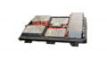
Analog Devices offers the DC2703A-A-KIT, a demonstration board for the LT8491.

The DC2703A-A-KIT. Image courtesy of Analog Devices
The Kit includes the DC2703A LT8491demo board and a DC1613A USB-to-I2C controller. A downloadable Microsoft Windows-Based GUI application dubbed the simpleLT8491 is available.