Facebook
 Google
 GitHub
 Linkedin
A Novel Half-bridge GaN Device for Enhanced System Performance
Gallium Nitride power switches continue to make inroads in diverse power conversion applications. One of the facilitators for this growth has been the responsiveness of GaN device manufacturers to diverse end-user requirements by providing targeted products that fit well into a given application.
When it comes to half-bridge (HB) power conversion topologies, there is a clear distinction between high-power, efficiency-driven applications and low-power, cost-driven applications. For the first type, Tagore Technology offers a set of devices with integrated-driver functionality. These devices interface very well with digital controllers as well as with dedicated analog controllers while offering a number of benefits from driver integration, including, but not limited to, efficiency improvements, better reliability, and a higher level of programmability.
However, at the other end of the spectrum, the low-power, cost-driven applications already have an existing ecosystem where there are well-established, highly integrated controllers and drivers that meet the customers’ requirements when used with silicon MOSFETs. For these applications, what is needed is a GaN solution that leverages this existing ecosystem and complements it by providing a highly integrated, compact GaN switching device.
Half-Bridge GaN Device
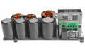
As shown in Figure 1, the TP44xx0HB, recently introduced by Tagore Technology, fulfills these requirements. The device is available in a 30-pin, 8×10×0.8 mm QFN package. It integrates two GaN switches: high-side (HS) and low-side (LS) needed for HB applications. The two switches are internally connected (the source of the HS switch to the drain of the LS switch), offering extremely low parasitics (both power loop parasitic inductance and parasitic junction capacitance). Additionally, thermal pads for both sources ensure low thermal-impedance cooling paths. Each of the switches is equipped with its own gate ESD structure to provide added protection. Finally, and most importantly, Kelvin connections for both switches ensure separation between the power loop and the gate drive loop for the HS and the LS, providing a safeguard against the Miller turn-on and the degradation in gate reliability. The TP44xx0HB is available in three different flavors, featuring GaN switches with Rds-on of 90 + 90 mΩs (TP44110HB), 180 + 180 mΩs (TP44220HB), and 360 + 360 mΩs (TP44440HB).
Circuit Benefits
The TPS44100HB has been specifically designed to simplify the circuit board layout and offer a slew of associated circuit performance benefits. The integrated package allows the shortest possible loop between the HS drain and the LS Source adjacent to the package, as shown in Figure 2. The suggested layout in Figure 2 also depicts that the required creepage distance of 2.8 mm is maintained in the IC as well as on the board. When using discrete switches, designers are often forced to make compromises between the optimum electrical layout and meeting creepage distances. The integrated device alleviates that concern. Further, the area of the pad connecting the drain of the LS to the source of the HS, which is the switched node of the half-bridge, is small enough to minimize parasitic capacitance to other planes but large enough for effective thermal performance.
.jpg)
Figure 1. TP44xx0HB – Functional Block Diagram (Left) and Device Image (Center, Right). Image used courtesy of Bodo’s Power Systems [PDF]

Figure 2. PCB layout diagram showing the suggested placement of the DC bus decoupling capacitor. Image used courtesy of Bodo’s Power Systems [PDF]
The pin-out of the TP44xx0HB has been carefully designed to provide ease of layout and significant flexibility. A number of pins and a large thermal pad are not electrically connected—allowing the flexibility to connect them to appropriate nodes/traces or leaving them unconnected, as desired. The most important feature here is the low voltage (± 20 V) isolation between the thermal pad and the source pins of the LS switch. This isolation allows one to place current sense resistors between the source pins and the power ground without compromising the connection between the thermal pad and the PCB of the power ground.
Product Design Constraints
In time-, space-, and cost-constrained product designs, there is a major incentive to use tried and tested components and a disincentive to make big changes to the system architecture. In such cases, the GaN device needs to be as easy to retrofit into the traditional silicon MOSFET -based designs as possible. While the integrated HB offers space and cost savings as opposed to discrete devices, it also offers a very easy interface with popular controllers (e.g., TEA2016 from NXP or NCP13992 from onsemi). These controllers typically include drive circuits for driving silicon MOSFETs, so the drive signal voltage levels are high and cannot be used directly with GaN switches. It is impractical to expect their interface to GaN to include a dedicated driver for GaN FET driving–that would be space and cost prohibitive.

Figure 3. Interface circuit for driving GaN switches from a PWM controller/driver. Image used courtesy of Bodo’s Power Systems [PDF]
Instead, Tagore Technology offers an extremely simple interface circuit, as shown in Figure 3. Here, DRV_H and DRV_L are the original gate drive signals with respect to their respective return signals RTN_H and RTN_L, coming out of the controller IC for the HS and LS switches. These signals are, however, of +12V/0V levels. On the other hand, the performance of the GaN switches greatly depends on the gate drive voltage levels. The interface circuit provides the optimal (reliable and efficient) drive levels for GaN switches (+6.2V/0V across the Gate and Source terminals). The 6.2V Zener diode clamps the gate-to-source voltage of each GaN switch to 6.2V, ensuring the reliability of the device. The resistors RU control the turn-on switching times of the GaN switches. The reverse Schottky diodes help speed up the turn-off times and avoid cross-conduction between the high- and low-side switches. The rest of the components either provide required biasing for the Zener diode or damping against any oscillations that might arise in the gate drive path. The separate Kelvin source of each GaN switch completely decouples the gate drive circuit from the power circuit.
Additionally, the pinout of TP44xx0HB has also been optimized for a direct interface to the TEA2016 and other similar controllers/drivers. Since the TEA2016 is a combo controller (PFC+LLC), it is the most challenging to interface with and will be used as an illustrative example. The utilization of a combo controller and an integrated device offers the highest level of integration and the lowest parts count that can be significantly beneficial to many cost- and space-constrained designs. The overall system reliability can also improve due to a reduction in the component count. By positioning the gate drive pins orthogonally on the package, the traces to each of the GAN switch gates from the TEA2016 can be kept separate. This results in a single-layer layout of the complete gate circuitry (HS and LS) without the use of any vias. There are multifold benefits of the single-layer layout: reduction in loop inductances, decoupling of gate signals from power signals, reduction in board size, and, most importantly, better thermal design. Multiple vias can compromise any heat-spreading efforts through the PCB layers and increase thermal impedances. The power trace layout is also simplified for both power stages.
Conclusions
The TP44xx0HB fills a gap for time-, space- and cost-constrained power converter designs by offering a unique, highly integrated, flexible, easy-to-use, and easy-to-interface GaN device. The system-level benefits accrued using this device include lower parasitics, higher reliability, better electrical performance, and improved thermal performance.
This article originally appeared in Bodo’s Power Systems [PDF] magazine and is co-authored by Asif Eqbal, manager of design, Rajesh Ghosh, chief power electronics engineer, and
Dhaval Dalal, systems applications architect, with Tagore Technology.
Featured image used courtesy of Adobe Stock