Facebook
 Google
 GitHub
 Linkedin
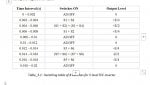
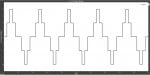
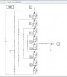
I built a five level Flying Capacitor Clamped (FCC) inverter in matlab simulink using Fundamental Frequency Shifting (FFS) switching technique. I chose 50Hz as fundamental frequency i.e. 20 ms is fundamental period which is divided into 10 segment (required level * 2). Here, the model schematic and the switching table for the switches is provided. By putting these values I got the desired 5 level stepped output which also provided here. But i couldn’t understand how the model operates actually like how the current flows, how flying capacitor and dc-link capacitor connected, how flying capacitor operates,and ultimately how we got the stepped output waveform. Particularly my problem is regarding how the voltage level E/4 is formed when S1 and S2 switches are on..
I am seeking kind help from the experts regarding this
I am seeking kind help from the experts regarding this
Attachments
-
 72.7 KB Views: 0
 -
 35.1 KB Views: 1
 -
 41.4 KB Views: 1