Facebook
 Google
 GitHub
 Linkedin
SiC in Industrial Auxiliary Power Supplies
This article highlights ROHM Semiconductor BD768xFJ control IC with the ROHM 1700V SiC MOSFET as part of principal circuit of the auxiliary power supply unit.
Any type of power conversion system (e.g. solar inverter, electric drive, UPS, HVDC) requires an auxiliary power supply to provide a low voltage bus of e.g. 12V or 24V to supply gate-drivers, microcontrollers, displays, sensors or fans for proper system operation. The auxiliary power supply will need to operate from either a three-phase 400/480V AC supply in case of typical industrial equipment or a high DC voltage in the case of a photovoltaic inverter.
SiC MOSFET for Compact Auxiliary Power Supplies
Figure 1 shows a typical circuit used for auxiliary power supplies. Depending on the input voltage, the MOSFET has to withstand up to 1300V. Since a certain safety margin is desirable it is common practice to use devices rated for at least 1500V. Si MOSFETs with this breakdown-voltage rating is available, but produce high losses and therefore require bulky, expensive heat sinks

Figure 1: Flyback as typical auxiliary supply topology
One option is to use more complex topologies to avoid the need for 1500V MOSFETs (e.g. a two-switch flyback or a series connection of lower voltage devices); however, this leads to additional complexity and increased component count.
The availability of 1700V SiC MOSFETs with a specific ON-state resistance approximately two magnitudes lower than that of 1500V Si MOSFETs (see Figure 2) offers the designer of an auxiliary power supply the option to use a simple single-switch flyback topology and achieve good performance with a compact design. ROHM Semiconductor offers high-voltage SiC MOSFETs suitable for this type of application in a surface mount package (TO-268-2L) as well as in a fully molded, isolated TO-3PFM package. These devices feature extended creepage distances of 5mm and 5.45m respectively.

Figure 2: Specific On-Resistance of Si and SiC MOSFETs
Control IC Enables Cost-effective SiC-based Single-switch Flyback Topology
The SiC flyback based auxiliary power supply solution gains further attractiveness by the availability of a control IC specifically designed to drive the SiC power MOSFET in this topology in a safe and reliable way without the complexity introduced by a gate driver IC.
With the BD768xFJ ROHM Semiconductor has released a quasi-resonant AC-DC controller IC that is compatible with several SiC MOSFETs available on the market today, in particular in terms of the gate-drive requirements of these devices. The best match for efficiency and performance is obtained when combining the BD768xFJ control IC with the ROHM 1700V SiC MOSFET. The BD768xFJ not only implements all the control for the flyback circuit but also takes care of driving the SiC MOSFET with suitable gate-voltage to ensure optimal performance. Additionally, the gate-clamp and overload protection features ensure the protection of the SiC MOSFET.
The control-IC BD768xFJ is housed in a compact SOP8-J8 package and offers a series of functions and protection features, including current sense with an external shunt, overload, input brown-out, and output overvoltage protection as well as soft-start. In the entire operating region, quasi-resonant switching is realized to minimize EMI and ensure low switching losses. To optimize operation at low load frequency-reduction modes as well as burst operation is implemented in the controller.
The principal circuit of a simple yet high performant auxiliary power supply unit based on the BD768xFJ control IC and a ROHM 1700V SiC MOSFET is shown in the following diagram.

Figure 3: Auxiliary power supply circuit using BD728xFJ control IC and 1700V SiC MOSFET
Performance of SiC MOSFET based auxiliary power supply
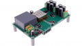
To show the performance that can be achieved with a simple auxiliary power supply based on SiC MOSFETs an evaluation board was developed (see Figure 4). In this circuit example the BD768xFJ-LB

Figure 4: Evaluation board for SiC-based auxiliary power supply unit
is used to drive a 1700V SiC MOSFET (SCT2H12NZ) in a quasi-resonant switching AC/DC converter. The quasi-resonant operation minimizes switching losses and helps to keep EMI low. The current detection is realized through an external resistor. Power efficiency is maximized by the use of the controller’s burst-mode operation and the reduction of the switching frequency under light load conditions.
Switching waveforms of the SiC MOSFET are shown in Figure 5. The waveforms at different output loads illustrate how the controller selects different valleys of the resonating drain-source voltage for turn-ON of the SiC MOSFET. This quasi-resonant operation minimises switching losses and EMI. After exiting the burst mode at very light load, the quasi-resonant mode is established and a high number of valleys are skipped before restarting a new cycle and switching on the transistor (left picture at Pout=5W).

Figure 5: Switching waveforms of SiC MOSFET in quasi-resonant operation
As the output power is increased, fewer valleys are skipped before restarting the cycle, which leads to an increase in frequency (Picture at Pout=20W). Close to the maximum defined output power (in this case 40W) the last valley is reached. The switching frequency reaches a maximum of 120 kHz at this point.
Higher demand in output power can be served with a slight decrease in switching frequency, to increase the ON-time of the primary switch. This increases the primary current peak and therefore the transferred energy (Picture at Pout = 40W). Above the maximum output power level, the overcurrent protection is triggered and the switching action is blocked to protect the system from overheating.
The board operates in discontinuous conduction mode (DCM) for the first two operating points and boundary conduction mode (BCM) is just reached the last operating point (40W). Depending on the input voltage the transition between DCM and BCM occurs at different output power levels.

Figure 6: Measurements conducted on SiC auxiliary supply unit
The efficiency for different input voltages across a load range of up to 40 W and an output voltage of 12V is shown in the diagram below. Throughout the measurements, as shown below, it was confirmed that the case temperature of the SiC MOSFET remains below 90°C. The maximum allowable junction temperature of the SiC MOSFET is 175°C.
Since the thermal resistance chip-to-case is much lower than case-to-ambient it is safe to assume in this case that the junction temperature is sufficiently lower than the limit, which confirms that operation of this board without a heatsink is possible at up to 40W output power. Higher output power can be achieved if a heatsink is used for the SiC MOSFET and cooling of the output rectification diode is improved.
While measurements with DC input voltages are shown here it is also possible to operate the evaluation board from a three-phase AC supply of 400/480V. The required diode bridge for line-rectification is implemented on the PCB.
SiC MOSFET technology allows designers to achieve improved efficiency, simplicity, reliability and compactness. Simple, cost-effective one-switch-flyback solutions for 3 phase input or with DC input voltages above 400V are not practical with Si MOSFETs at some tens of Watts of power due to the poor
The superior performance of 1700V SiC MOSFETs and the availability of the control IC family BD768xFJ allow the design of simple auxiliary power supplies for 3 phase systems or for systems with high DC input voltage with good performance. The SiC MOSFET technology allows designers to achieve improved efficiency, simplicity, reliability and compactness. This can be achieved at a system cost comparable to Si MOSFET solutions as a result of the performance benefits of the 1700V SiC MOSFET.
In addition, the cost of expensive components such as heatsinks and magnetics can be reduced. The control IC is optimized to safely drive the SiC MOSFET to help realize a very simple solution that reduces the design effort and minimizes the time to market of the system.
An application note with more detailed schematics, a dimensioning guide, and a component list, as well as further information, is available on the ROHM website. Evaluation boards illustrating the operation of the matched combination of control IC and SiC MOSFET for auxiliary power supply units can be obtained by contacting ROHM Semiconductor GmbH.
About the Authors
Christian Felgemacher received the MEng (Hons) degree in electronics and electrical engineering with management from the University of Edinburgh in 2011 and the Dr.-Ing. Degree from the University of Kassel in 2018. He worked as a Research Assistant at the Centre of Competence for Distributed Electric Power Technology (KDEE) at the University of Kassel from 2012 to 2017. During this time he worked on reliability aspects of power semiconductors in PV inverters and the utilization of wide-band-gap devices in renewable energy applications. Since April 2017 he is with ROHM Semiconductor and is currently supporting European customers as Field Application Engineer for power semiconductors.
Walter Balzarotti holds a Degree in Electrical/Power Electronics at Politecnico di Milano. He is particularly skilled in integrated circuits, semiconductors and sensors and is an experienced Application Engineer with wide experience in the power management semiconductors industry. Solid professional skills in Device Drivers, Silicon Carbide, Sales, Analog Circuit Design, and Power Supplies. He worked at ROHM as a Field Application Engineer and is now working at Infineon Technologies as an Application Engineer for Digital Isolators PWM.
Bastian Lang holds a Dipl. -Ing in Electrical and Computer Engineering from the Regensburg University of Applied Sciences and is skilled in the field of power electronics, power management and product development. He is currently the manager of product marketing at Infineon Technologies. Lang's focus is on power management and product development. Lang worked with ROHM Semiconductor, the PULS Group, and Integrated Device Technology before joining the Infineon Technologies team.
This article originally appeared in the Bodo’s Power Systems magazine.