Facebook
 Google
 GitHub
 Linkedin
How to Achieve Fast Switching with a High-Voltage Isolated Driver IC
In high switching frequency applications, the high commutation slopes of the power switches require immunity against high levels of common mode noise. In addition, isolation capability and very short signal propagation delay are also typically required.
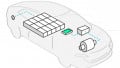
Industrial systems have struggled in recent years with the need of high efficiency, combined with the need of more compact systems. This also influences the choice of the gate drivers associated to high speed switches, like Silicon Carbide (SiC) MOSFETs. STMicroelectronics has recently launched the STGAP2, a family of isolated gate drivers focused on the industrial power market. Its portfolio includes different isolation voltages and functionalities.
Isolated gate drivers are widely used in industrial power applications. In high switching frequency applications, the high commutation slopes of the power switches require immunity against high levels of common mode noise. In addition, isolation capability and very short signal propagation delay are also typically required.
The STGAP2S product family [1] [2] , from STMicroelectronics, offers isolation through a coreless transformer, with propagation delay of 80 ns. In addition, it has an immunity against common mode above 100 V/ns. The isolation between primary and secondary sides is tested up to 1.7 kV. All this in a very compact package: the single channel driver is available in SO-8N package, while the STGAP2D - dual channel – is available in SO-16N package. The is offered in two variants: one STGAP2SCM, with active Miller clamp (AMC), and STGAP2SM, with separated on- and off- outputs. The comparative table of all devices from STGAP2 technology is shown below in Table 1.
The devices from the STGAP2S family have 4 mm creepage distance between primary and secondary sides. For some applications, there might be the need of higher creepage distances, depending on pollution degree and maximum humidity levels.
In these cases, STGAP2HS [3] family is indicated. It is offered in an SO-8W package, with 8 mm creepage, allowing the gate drivers from this family to be tested with 6 kV.
In addition, this family also includes dedicated part numbers for operation with SiC MOSFETs, namely STGAP2SiCS [4] . They have increased values of under voltage lockout (UVLO) to couple with the higher operation gate voltage of those switches.
Common Mode Transient Immunity
Fast power switches applied in industrial applications can present slew rates above 50 V/ns. This is a desired feature to reduce dynamic losses and achieve higher system efficiency. Fast transients can generate disturbances in the associated gate driver though. In high side drivers, the fast transient in the secondary side can generate oscillations in the primary ground. In the worst case, this may cause glitches in the input signal, and consequently, the unwanted switch on of the SiC MOSFET.
Figure 1 shows experimental results with the STGAP2S device during very fast transients, both positive and negative, with a DC voltage Vdc=1500 V. The waveforms demonstrate that, even for slew rates in the order of 120 to 130 V/ns, the gate driver was able to properly operate and maintain the desired output state.
Coupling Through Miller Capacitance
High slew-rate transients in the Drain to Source voltage can also cause oscillations in the gate through the Miller capacitance (MC) i.e. the parasitic capacitance between Drain and Gate of a MOSFET. To minimize it, one of the variants of the STGAP2S, the STGAP25CM,offers an active Miller clamp (AMC), see Figure 2.
| Part number | # Channels | Package | Isolation | UVLO | Output Conf. |
| STGAP2SM | Single | SO-8N | 1.7 kV | 9.1 V | Separated on/off |
| STGAP2SCM | Single | SO-8N | 1.7 kV | 9.1 V | Miller Clamp |
| STGAP2D | Dual | SO-16N | 1.7 kV | 9.1 V | Single Output |
| STGAP2HSM | Single | SO-8W | 6 kV | 9.1 V | Separated on/off |
| STGAP2HSCM | Single | SO-8W | 6 kV | 9.1 V | Miller Clamp |
| STGAP2SiCS | Single | SO-8W | 6 kV | 15.5 V | Separated on/off |
| STGAP2SiCSC | Single | SO-8W | 6 kV | 15.5 V | Miller Clamp |
Table 1: Product portfolio of STGAP2 Technology.
1 more details on the isolation voltage in a dedicated section.
² referred as the typical value of the turn-on threshold, as stated in the datasheet.

Figure 1: Measured positive and negative transients in the STGAP2S, VDC=1500V.
The AMC is a recommended functionality for use with SiC MOSFETs in applications where fast hard-switching transients are expected. Figure 3 depicts idealized waveforms of a half-bridge inverter using the SCTW35N120G2V, a 650V rated SiC MOSFET from STMicroelectronics [6] . As the output current is assumed positive, the low side switch (S2) is turned-on during the free-wheeling time. After a short dead-time after the turn-off of S2, the high side switch S1 is turnedon. When this happens, the VDS of S1 goes to zero, causing the VDS of S2 to increase. Both transients have same slew-rate. The gate voltage VGS of S2, which was in OFF voltage, is now pulled up by the coupling through Miller capacitance. In the same way, VGS is pulled down when S1 turns off. Symmetrically, the same kind of oscillations are expected in S1 when output current is negative.

Figure 2: Available options of the STGAP2S.

Figure 3: Half-Bridge inverter with SIC MOSFETs, and idealized waveforms of VDS and VGS.

Figure 4: VGS waveforms in the half-bridge inverter, using two variants of the STGAP2S.

Table 2: Voltage characteristics of the STGAP2H devices in SO-8W package.
Both positive and negative oscillations in VGS during OFF state can have a negative impact on the device and the system. Positive oscillations can cause parasitic turn-on of the MOSFET, and consequent shot-thru of the entire half-bridge. On the other hand, negative oscillations may bring VGS outside of the safe operation area (SOA), and trigger degradation mechanisms in the device.
As can be seen by the waveforms in Figure 4, the ACM is able to reduce both positive and negative spikes of VGS during off state, down to safe values. As it can be shown, when driven by the STGAP2SM, the VGS of a SiC MOSFET can achieve positive values, with the consequent risk of parasitic-turn-on. With the STGAP2SCM, the same configuration presents much lower spikes, which never reach positive values.
In the same way, the negative oscillations in the right side of Figure 4 are also reduced. The configuration with the STGAP2SM presents negative peaks below the absolute minimum gate voltage, which lays at VGS,min=-10 V for the SCTW35N65G2V. With the STGAP2SCM, the negative spikes never reach VGS,min.
Isolation voltage
The gate drivers inside the SO-8W package – refer to Table 1 – have an isolation of 6 kV. This voltage is related to the test voltage during production, in accordance to UL1577. More details on the voltage characteristics of the STGAP2H family in SO-8W package are shown in Table 2.
Undervoltage Lock-out (UVLO)
The undervoltage lock-out (UVLO) is a protection feature, present in all STGAP2 devices. It prevents the power switch from being driven with a voltage below its requirements. The UVLO protection is activated when the supply voltage of the secondary side, i.e. the voltage between pins VH and GNDISO, drops below a certain value.
IGBTs and super-junction MOSFETs operate with gate voltages between +12 V and +15 V. Below this range, the on-resistance of the MOSFET – or the saturation voltage of the IGBTs – starts to increase, and with it the conduction losses of the switch. The switch could also start to operate in linear mode, leading to thermal runway and to device failure. The same can also occur in SiC MOSFETs. However, due to the required higher voltage on the gate – from +18V to +20V, - the value at which the UVLO is activated needs to be increased accordingly.
Figure 5 presents the output characteristics of the STW90N65G2V [5]. The V-I curves on the graph are obtained for different values of gate-to-source voltages VGS, at room temperature. The values below the graph are the calculated power dissipation due to current conduction, at a drain current of 40 A. For VGS = 18 V, the nominal value for this device, the resulting dissipation is around 28 W.

Figure 5 – Output characteristics of SCTW90N65G2V SiC MOSFET, and calculated conduction losses for different gate-tosource voltages.
If the power supply on the gate driver drops, this will affect VGS as well. On the graph we have the example for VGS = 12 V, that would already increase the conduction losses almost double. Going even further down will cause the MOSFET to operate in linear mode. The extremely high associated losses can cause the MOSFET to fail due to overheating.
To avoid that, the UVLO of the STGAP2SiCS [5] devices has been increased to 15.5 V. This guarantees proper protection even if bipolar drive is applied to the MOSFET. As an example, if a negative off voltage of -3V is applied to the MOSFET, this will bring the effective activation voltage down to +12.5V, still safe enough for SiC MOSFETs.
Summary
The devices in the STGAP2 technology family enable operation at very high switching speeds, and in turn, enabling high power density of industrial systems. Among their very interesting features are CMTI above 100 V/ns, typical propagation of 80 ns, and active Miller clamp functionality. The newest STGAP2HS is offered in an SO-8W package, which allows a higher isolation voltage of 6 kV. Specifically designed for combination with SiC MOSFETs, the STGAP2SiCS has an increased UVLO value, to guarantee its proper protection function.
About the Author
Vladimir Scarpa is working as a Field Application Engineer at ROHM Semiconductor, an electronic parts manufacturer company with its main branch based in Kyoto, Japan. He was born in Uberlândia, Brazil, in 1980. He received the B.Sc. and M.Sc. degrees in electrical engineering from the Federal University of Uberlândia, Uberlândia, in 2003 and 2005, respectively. His research interests include power electronics applied to renewable energy sources and digital control of switching power supplies
Jan Svetlik is an application engineer and worked as a Technical Marketing Manager at STMicroelectronics.
Michele Lauria received his Masters of Electronic Engineering at the Polytechnic University of Milan. He now works as a Senior Application Engineer at STMicroelectronics, which is a global semiconductor leader delivering intelligent and energy-efficient products and solutions that power the electronics at the heart of everyday life.