How Thermal Environment Impacts Power Supply Success
How Thermal Environment Impacts Power Supply Success.
Operational temperature range can make or break a design. Choose wisely.
Selecting the right AC/DC power supply for a given application starts with the environment. A power supply that is intended to spend its operational life in an office cubicle will clearly be subject to a different set of design challenges than one that will be potted into an enclosure and mounted to the side of an industrial irrigator.
Many physical properties of circuit elements and the media that surround them are in fact functions of environmental factors such as ambient temperature, air pressure, humidity, pollution degree, etc. Changes in ambient temperature can also affect the behavior, performance, and reliability of power supplies, making understanding the power supply’s operational temperature range crucial to the success of the design.

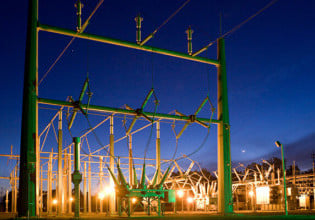
Image 1: Although air pressure, pollution, and humidity can all be environmental factors in the operational function of power supplies, temperature range is crucial to the success of power supply design.
Where to Begin
The implications of operating power supplies at extreme temperatures are certainly key concerns in the design phase. But first, let’s define some basic, expected operating ranges for two of the most common types of power conversion products: AC/DC power adaptors and internal AC/DC power supplies. While there is no one single standard for operational temperature range (nor for thermal derating), the following offer a rule of thumb for the industrial, commercial, and medical markets. Other markets may be expected to observe different generic ranges:
AC/DC Power Adaptors (Wall Mounts and Desktops)
The typical AC/DC power adaptor, enclosed in a plastic case, can be expected to offer its full nameplate-rated output power in ambient temperatures between 0°C and 40°C (32°F and 104°F). This range is ideal for devices used indoors—in an office, home, or similar setting—where people work or live. Most people are not interacting with electrical office equipment or hospital equipment in environments outside this range. These types of power converters can usually operate safely and reliably in environments between 40°C and 60°C with appropriate derating considerations.
$$P_{AVAILABLE} = \begin{cases} P_{RATED} & ; 0^{\circ} < T \leq 40^{\circ}C \\ P_{RATED}(2.25-0.025T) & ; 40^{\circ} < T \leq 60^{\circ}C\\ 0 & ;T > 60C^{\circ} \end{cases}$$
Internal AC/DC Power Supplies (Open Frame and Enclosed):
Open frame power supply thermal derating curves often carry one additional caveat, especially when dealing with super-100W systems. That caveat is the presence of conduction or convection based cooling mechanism. It is not uncommon to see open frame derating curves with multiple traces, each for different cooling considerations, and/or different output voltages. Lower voltages represent higher currents and higher currents translate to greater dissipation. Most higher-power open frame power supplies are rated under the assumption that a prescribed volume (usually between 20 and 40 CFM) of forced air will be provided to push hot air away from the surface of dissipative elements. Without this airflow, the available output power can be expected to suffer by as much as 40 or 50%. Further discussion on convection cooling will be provided later in this article.
It warrants reiteration that these functions are generic and are presented to further this article's discussion on environmental factors, but that manufacturer data sheets should always be consulted before making formal design decisions.
The typical internal AC/DC power supply can be expected to offer its full nameplate-rated power output in ambient temperatures between 0°C and 50°C (32°F and 122°F). It is also rather common to see open-frame converters with lower temperature reaches well below 0°C. This range spawns from the assumption that the devices are being operated in some enclosed end device that may house other dissipative elements and may offer limited means for generated heat to escape. Further, the possibility exists that the internal supply may be used in an end device designed for use outdoors or in more extreme environments than a home or office. These types of power converters can usually operate safely and reliably in environments between 50°C and 70°C with appropriate derating considerations.
$$P_{AVAILABLE} = \begin{cases} P_{RATED} & ; 0^{\circ} < T \leq 50^{\circ}C \\ P_{RATED}(2.25-0.025T) & ; 50^{\circ} < T \leq 70^{\circ}C\\ 0 & ;T > 70C^{\circ} \end{cases}$$
Low-temperature operation concerns
Power supply performance is degraded at sub-specified temperatures via two primary mechanisms: “self-removing” inrush current limiting devices and electrolytic capacitors.
Inrush Current Limiting Devices
When the rectified high voltage (HV) rail rises rapidly from 0VDC to √2•Line upon application of AC, the bulk capacitor on the primary of the switch-mode power converter (SMPS) acts as a short circuit, drawing large amounts of current, known as inrush current, as the capacitor begins to charge. Excessive inrush current is undesirable, and so efforts are made to mitigate it.
One common strategy is to place an NTC thermistor in series with the bulk capacitor. Care is taken by the design engineer to ensure that the chosen thermistor maintains an appropriately high impedance at the upper limits of the PSUs rated temperature range to mitigate inrush currents, while still maintaining an appropriately low impedance during steady-state, light load operation at the lower limits of the PSUs rated temperature range. For a given design, there exists an ambient temperature below which the input impedance will be too large for the converter’s start-up circuit to pull the needed amount of current off the HV rail to initiate a successful start-up
Electrolytic Capacitors
At typical SMPS switching frequencies, the inductive nature of the mains lines effectively limits the available current that can be supplied to the converter. Accordingly, a local energy store (bulk capacitor) with low HF impedance is needed to receive and store the incoming 50 or 60Hz energy, while simultaneously providing energy to the downstream conversion network at a much higher frequency. One of the earliest PSU design determinations is just how much energy needs to be stored in this bulk capacitor to support the stable operation. As the temperature of the electrolyte within an electrolytic capacitor decreases, its viscosity increases, resulting in a degradation in electrical conductivity. This drop-in electrolyte conductivity ultimately manifests itself as a decrease in capacitance of the structure. Accordingly, there exists a temperature below which the available HF energy is insufficient for the stable operation of the converter. E-caps are also used widely in the output filter to reduce voltage ripple. As the capacitance in the filter decreases with temperature, the ripple increases and may become unsuitable for some applications.
Turning up the Heat
Heat is a power converter’s worst enemy. At high operational temperatures, thermal runaway can cause semiconductors to overheat and burn out. Component temperatures may exceed those permitted by applicable safety standards, and a device’s operational lifetime can be cut short as chemical processes are accelerated.
Further complicating this is the fact that power supplies generate heat as a byproduct of normal operation. This occurs when functional or non-functional currents pass through any element with a real impedance, such as diodes and transistors, PCB traces, transformer windings, even transformer cores (eddy currents). The heat generated by a power supply is related to its operational efficiency.
$$Q_{d} = P_{OUT_{0}} \left ( (1/\eta _{0})-1 \right )$$
Where Qd is the heat dissipated in Watts, POUT is the output power in Watts, and η is the efficiency. POUT and η have been assigned like subscripts to make clear the fact that the operational efficiency varies with output power and is not just some fixed value.
Heat is transferred out of a power supply through a combination of all three heat transfer mechanisms: radiation, conduction, and convection, but primarily via the latter two. If there is a disparity between the heat generated and the heat transferred, the device’s temperature will rise according to the equivalent thermal impedance between it and the cooler environment. To prevent component temperatures from rising to levels that adversely affect their reliabilities or safe operation, the power supply must be designed to allow generated heat to escape (by reducing the thermal impedance between heat sources and the ambient environment), and also perhaps in a manner that minimizes the amount of heat generated in the first place.
The Origin of Thermal Derating
Given that the heat transferred from a PSU to the ambient environment is directly proportional to the difference in temperature between the two media by some constant k determined by the material properties, and that the average rise in temperature of the PSU is proportional to the heat generated (function of efficiency and throughput) less the heat transferred, one can assert:
$$\Delta T_{C} \propto P_{OUT_{0}} \left ( (1/\eta _{0})-1 \right )- k(T_{1}-T_{2})$$
Where T2 is the ambient temperature, T1 is the temperature of the PSU, and ΔTC is the PSU temperature rise. The above equation tells the ambient temperature surrounding it increases. As T2 approaches the value of T1, ΔTC rises. That is, as the ambient temperature of a power supply approaches its internal temperature, the ability of the components to transfer their self-generated heat out to the ambient environment diminishes.
Convection Heat Transfer and the Origin of Convection vs. Forced Air Ratings
Convection is the transfer of heat via the movement of fluids, including air, across the surface of an object with a temperature different than that of the fluid. Convection heat transfer can get a good deal more complex than conduction in the context of power supply cooling. The key takeaway is to understand that conduction does not work alone to remove heat from inside a power supply; conduction simply brings the internally generated heat out to the surface of the power supply. From there, we depend on convection to “carry” the heat away from the supply into the ambient environment.
Consider for a moment a situation whereby the air directly abutting the surface of a power supply is somehow disallowed from moving. As the air stays in proximity to the hot power supply surface, its temperature will rise. Eventually, the temperature will become equal to the temperature of the power supply surface. There is once again a dependence on a temperature differential between the two media. If the fluid (air) and the power supply (the hot object) are the exact same temperature, no heat will be transferred. Without allowing heat to move away from the outside of the power supply, its temperature will begin to rise as well, further impeding the effects of conduction. Fortunately, the air is not inclined to stay in one static location, particularly in the presence of temperature gradients throughout the fluid. As they say, “warm air rises.” Indeed, as the temperature of the air nearest the warm power supply increases, the density of the air decreases, causing cooler, denser air to “sink in” and take its place.
Tackling Density
For some power supplies, the natural process of convection is sufficient for maintaining an adequate temperature differential between the power supply’s outer surfaces and the air for appropriate heat transfer. However, the rate of heat transfer via convection, not unlike conduction, has a dependence on interface area, or how much surface in squared meters is actually in contact with the fluid.
The power supply industry, alongside many of the industries it supports, strives to achieve greater functional densities. One of the strongest ongoing industry trends is to develop technologies that allow us to put more and more power into smaller and smaller packages. Recall that, in general, as output power increases, the amount of heat generated increases as well. Combining this with the fact that the ability of convection to remove heat from the surface of a power supply is dependent on the size of the power supply and its effective contact area reveals the need for forced-air cooling in many of today’s modern, high-density power converters. The natural process simply isn’t fast enough to maintain adequate heat transfer rates and prevent internal components from overheating.
Choosing Wisely
Ambient temperature impacts the behavior, performance, and reliability of power supplies, making the environment a critical factor in their selection. By understanding industry conventions and popular cooling methods, factors that underscore a power supply’s operational temperature range, thermal derating curves, and what to expect if thermal limits are exceeded, designers are well equipped to make the right choice.
About the Author
Dylan Howes worked as an Applications Engineer at TT Electronics Power Partners, Incorporated that is a TT Electronics company. He manages all technical aspects of power converter design-in efforts, and the author's technical content featuring power conversion trends and technologies.
This article originally appeared in the Bodo’s Power Systems magazine.


