Facebook
 Google
 GitHub
 Linkedin
Advanced Validation of Magnetics for High Power and Energy Applications
Analytical models regarding magnetic components` performance, cored with discrete distributed multi gapped design, are far away from satisfied, which significantly limits the high power and energy applications.
Even the efforts undertaken where the modeling for the air-gapped core was built can be found in [1] and [2], the discussion only cover the length of air-gaps is relatively small (the ratio between the air-gap and the entire effective magnetic flux length is approximately in the order of 10-4 for grinding and for 10-5 lapping & polishing, mainly for signal processing application. Thus the measurement validation for the components, such as by following standard IEEE 393, takes the role to provide credible design and application reference. In this article, we propose utilizing the novel damp-oscillation method by Bs&T pulse to measure and analyze the next-generation power and energizing magnetic components in range of kW & MW for traction & MV dc grid. The discussion-based on case study covers more based on the large airgap length (the ratio increases to order of 10-2 e.g. the calculated effective permeability in range of 2 digital. Two key parameters, the sheared permeability, and the apparent permeability, to qualify the component performance, shift from the material & core, are discussed. The precise, robust, and easy measurement under defined large energizing conditions shows much better treatment of the difference between cores and the components and enables specification measurement with limit value.
Uncertainty From Known Modeling
The concept of distributed air-gaps in the magnetic core has been proposed for decades while the understanding is reduced with keyword flux fringing. However, the cost countering the benefit from the concept is controversial, mainly for the complexity of hardware implementation and the difficulty of design and performance estimation. In any case, the reluctance model is the most popular and simplest modeling for the component designers, where the material is regarded as structural homogeneous and magnetic isotropic, whereas the saturation behavior is simplified as a saturation magnetic flux density, rather than an incremental process, where the density is manipulative because the effective cross-section is unknown. However, the magnetization process from the materials science, or the magnetism in condensed matter`s view, is way more complicated, by giving the demagnetization factor, either in internal demagnetization factor and external demagnetization factor of great relevance[5].
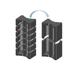
Figure 1. A demonstration for distributed and single air-gap core from Shandong Dongtai Electronics Co.
It is well known that the materials in the magnetic cores are impossible to model for the magnetic features and the loss estimation, even the model for the homogeneous magnetic material has been discussed for tens of years. Within different types of cores (such as ferrite cores, metal alloyed powdered cores), the submicron crystalline structure of the magnetic materials and the filling material makes it difficult to apply only one theoretical models and also the manufacture process and induced uncertainty even discourage any attempt to model the commercially available magnetic cores. In general, the impact to shape the cores` performance can be only validated by external demagnetization factor, as well as percolative behavior for powdered composite due to internal demagnetization factor only by measurement [5].
Particularly for the gapped magnetic cores, priority-arts can be found, including the McLyman`s method, where the gap-length was corrected based on simplified wire configuration and the core shapes but the results only valid when the gap-length is relative low (the lg/le is within the order of 10-4 ), and the Alex van Bossche`s method, taking consideration of bobbin and wire configuration for selected cases, where the effective area for the magnetic loop was corrected empirically. For the other applications, core shapes and emerging materials, people still know little and has no modelling for the estimation and rely on personal experience and know-how with singular project and temporal mood. Besides, few works mentioned that the position of the winding even shape the magnetic flux in the component, rather than only by the core shapes.
The finite-element-analysis (FEA) simulation is a powerful tool to estimate performance for gapped cores for designers. As shown in Figure 2, which is an illustration for the discrete gapped core, the performance of the winding and the core can be precisely reflected by numerical solution but only after the core performance has been known well. Obviously, the FEA cannot distinguish the macroscopic structure for different material (such as between powder element and ceramic grain in a core). Thus the measurement is the only way to provide design and manufacture reference as well as for the component validation, under the circumstance where no analytical model for both materials and general magnetic cores.
Bs&T Damp-Oscillation Solution
The basic concept for damped oscillation method in Bs&T pulse micro can be found in [3][4]. In the first place, the energy (in range of 1~200 Joule) for damped oscillation will be charged in the capacitor where the voltage can be controlled from 100 V to as high as 1000V to provide precisely energy for the oscillation. Once the capacitor being charged, a damped oscillation will be conducted on the D.U.T., during which the voltage and the current of the D.U.T. will be sampled and processed to achieve the performance evaluation, and will complete inductance analysis for magnetization and demagnetization path. In this demonstration, the distributed gapped toroidal cores were tested and evaluated by the set-up to reveal their performance and the results will mainly provide the sheared permeability (reset gain) and the apparent permeability as evidence for the gapped toroidal cores, especially to adapt the modern applications with different configuration, where lg/le is mechanically fixed in the order of 10-2. The toroidal shape is chosen for its asymmetry, even in practices, only the middle part is locally multi-gapped (see Figure 1).
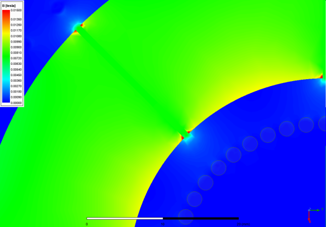
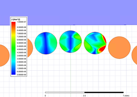
Figure 2. A demonstration of flux density and current distribution for gapped core by FEA simulation
The parameters of the magnetic core in the case study is shown in the table and the photo of the core with 8 air-gaps is also shown.
| Item | Parameter |
| Outer Diameter | 92.5mm |
| Inner Diameter | 52mm |
| Height | 40mm |
| Number of Turns | 10 |
During the test we kept the exactly same winding configuration and measurement condition, e.g. impulse energy, but the air-gap are distributed in one, two, four and eight pieces to distinguish the performance. Obviously with the conventional reluctance model the performance is expected same, while the difference can be observed by our damp-oscillation solution.
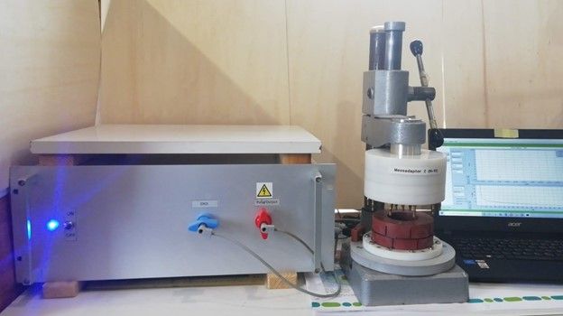
Figure 3. Device Under Test cored with discretely distributed multi gapped (8 gaps/ 0.7 mm for each) toroidal shape, adaptor with defined wire & number, number of turns(10) and its terminals in experimental set up with BsT-pulse micro ( with friendly support by Tridelta Weichferrite GmbH)
Apparent Permeability
In the first place, we measured the differential inductance for the different configuration of ferrite element as gapped core for the same total air gap length, as in the Figure 4. In Figure 4 (a), the excitation current varies up to approximately 1300 A, where as the saturation process can be fully mapped. It is obviously found that the nonlinear saturation branch at the lower current area while merge as one inductance curve at a higher excitation area. In the Figure 4 (b), a zoom-in figure highlights the differential inductance difference, which can come up to one sixth of the initial inductance.
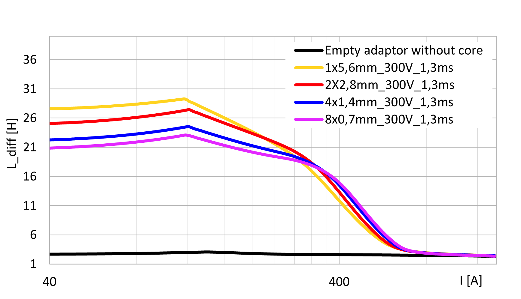
Figure 4. Measured inductance for the distributed gapped toroidal core.
Then a key definition, the apparent permeability should be introduced here, to normalize the shifting of the core. The concept of the apparent permeability is to separate the impact of the magnetic element, regardless which element how configured within the defined winding topology, thus the apparent permeability is normalized by the measurement of the device without the magnetic element core, but only of the windings. In Figure 5, the measured pulsed amplitude permeability [IEEE 389] of the devices are plotted as the function of the magnetic flux density. Interestingly, the pulse amplitude permeability for the devices reduce with the increasing of the number of gaps, though the total length of the air-gaps are all the same as 5.6 mm. However, when the saturation dominate the operation, the permeability merge as one curve and the impact of the air-gaps fade along the higher magnetic flux density. Correspondingly, the apparent permeability can be get as shown in Figure 6 (a) and (b) for both the magnetization and de-magnetization process. It is found that not only the number of the air-gaps would influence the apparent permeability, but also the mag- and de-mag process will also shift the permeability thus the true operation is much more complex to be modelled by simplified equation.
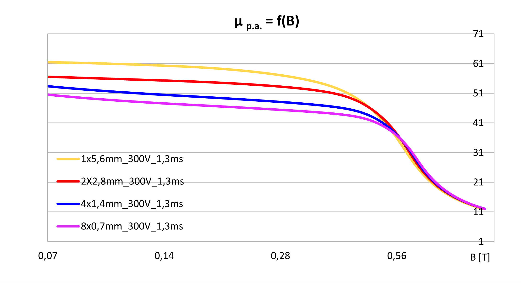
Figure 5: Measured pulsed amplitude permeability as a function of the magnetic flux density
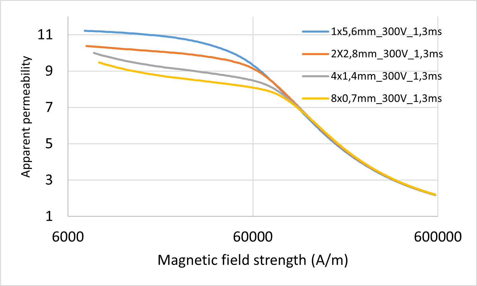
Figure 6: Apparent permeability during magnetization and demagnetization process
Sheared Permeability (Reset Gain)
Another valuable term called reset gain can be initially found from IEEE standard 393-1991 as ...
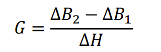
where two points can be selected on the B-H curve measurement by the measurement with pulsed excitation. This reset gain can be normalized to sheared permeability with absolute permeability value in vacuum, which has very similar definition by using magnetic flux density divided by the magnetic field strength. Hereby in our post-processing given by fact that demagnetization and magnetization are parallel at origin starting point of hysteresis by large gap, we selected using sheared residual induction Br at current zero-crossing point and coercive force Hc by definition also delta B=0.
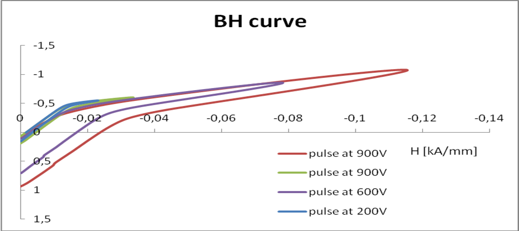
Figure 7: Demagnetization curve around the first current peak comparison with different initial energy
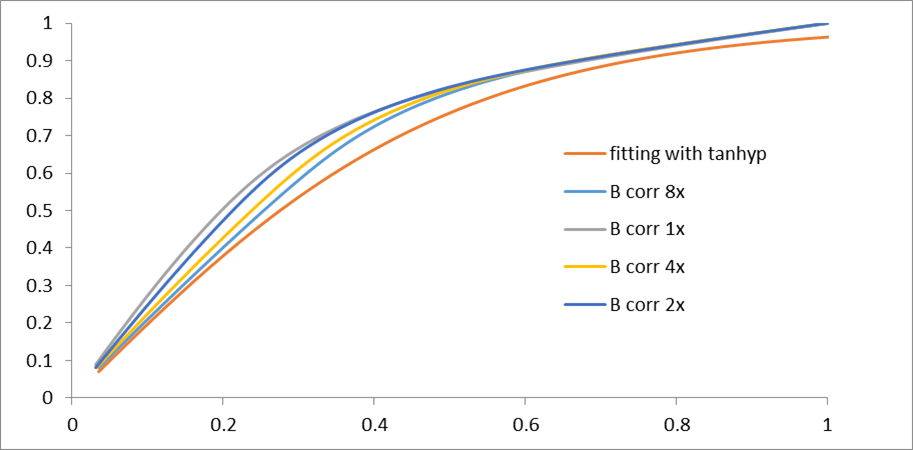
Figure 8: Demagnetization curve comparison among different air-gap configurations 8(a) overviewed (b) normalized with fitting function of tanhyp
During the testing we implement different initial oscillation voltage on the capacitor (200 – 300 – 600 – 900 V), thus the four half B-H loops show in different shapes, however the Br and Hc locate on the same position. It indicates that the energy stored in the components won`t shift the reset gain. So this measured value under same energizing condition qualified as the permeability to evaluate the component performance, together with apparent permeability. Care needs to be taken for interpretation of coercive force, the demagnetization is included, percolative behavior for composite for internal demagnetization factor (micro, meso agglomerates) for large filling factor, and external demagnetization factor of core shape, in this particular investigation, toroidal shape is taken.
Last but not least, the comparison between each demagnetization curve is illustrated in Figure 8. In Figure 8 (a), an overviewed demagnetization curve comparison is given, from which it is found that the saturation process for each configuration finally merge into a vacuum permeability. Actually, the core with the single largest air-gap “feigned” larger inductance, at beginning and comes into saturation at latest. The demagnetization factor of this configuration is effectively different as others, the more incremetal parts distributed along the circumference, the closer it convergents to fixed value, this is illustrated in Figure 8(b).
All these new observations indicate that though the distribute airgap cores are challenging to be modelled, but based on the damposcillation method, the features can be unearthed and qualified for further analysis. Besides, with the similar measurement method, the temperature dependence features and the aging effect can be also conducted for the distributed air-gap cores. In fact, the potential and the performance of the distribute air-gap core are still waiting for further development. Last but not least, the quality factor, which can reflect the loss performance for the magnetic components, can also be measured with the proposed method [3].
Summary
Bs&T Damp-Oscillation Solution brings validation method two-parameter under large excitation; apparent and sheared permeability, to characterize the magnetic designed with discretely distributed multi gapped toroidal cores with larger ratio lg/le ~ 10-2. With the measurement set-up, new features, new design reference and new modelling method are on the way to face the emerging power & energy electronics applications.
References
[1] Snelling, E. C., & Giles, A. D. (1983). Ferrites for inductors and transformers (Vol. 136). New York: Research Studies Press.
[2] Valchev, V. C., & Van den Bossche, A. (2018). Inductors and transformers for power electronics. CRC press.
[3] Sun, JC & Dou, (2020). Damp-Oscillation Solution for Validation of the Metal Alloyed Powder Core. Bodo’s Power Systems.
[4] Sun, JC & Dou, (2020). Hanna Curve Reloaded. Bodo’s Power Systems.
[5] Mattei, J. L., & Le Floc, M. (2003). Percolative behaviour and demagnetizing effects in disordered heterostructures. Journal of Magnetism and Magnetic Materials, 257(2-3), 335-345.
This article was co-authored by JC Sun and By JC Sun and Yi Dou. This article originally appeared in Bodo's Power.