Facebook
 Google
 GitHub
 Linkedin
Enhanced Trench 3300V TSPT+ IGBT Module Brings Highest Current Density and Robustness
This article discusses the Enhanced Trench cell or TSPT+ technology and its features and advantages.
With the arrival of the Enhanced Planar (SPT+) IGBT cell technology, ABB set a benchmark in device performance that still today competes with Trench cell IGBTs. Nevertheless, the market continuously demands increased performance. ABB has thus combined the merits of the enhanced planar cell with trench technology and created the Enhanced Trench TSPT+ IGBT. The new 3300V TSPT+ represents the latest generation of IGBT cell technology, enabling a further loss reduction and hence the possibility to increase the current density.
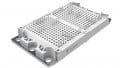
With the new device, the HiPak2 (140 x 190mm2) can be rated at 1800A. This has a 20 percent increase in current density over the previous SPT+ generation rated at 1500A. Alongside reduced losses and increased current density, robustness is an important consideration for demanding power electronic applications like traction and transmission and distribution (T&D). A higher voltage Trench cell designs are known to suffer from so-called degradation effects. Because of this, ABB has invested time and resources to mitigate Trench cell degradation without compromising on device performance and the result was the launch of the 3300V, 1800A TSPT+ IGBT at PCIM 2018 in Nuremberg.
The Latest Generation Technology: IGBT Cell Technology
The combination of the Enhanced Trench cell IGBT builds on the N-type enhancement layer and Trench technology results in an Enhanced Trench cell or TSPT+ technology (see Figure 1).

Figure 1. The Enhanced Trench (TSPT) cell
The TSPT+ cell is implemented as a stripe design and to achieve the targeted enhanced carrier concentration near the trench emitter (the aim for this is to reduce conduction losses) the TSPT+ cell is combined with the characteristic N-enhancement layer. This greatly reduces the hole drainage through the cell. The P-well between the trenches is designed to achieve a low input capacitance making an optimized IGBT turn-on behavior to support the blocking voltage. The P-well is resistively coupled to the emitter node in order to optimize the trade-off of controllable turn-on and conduction losses.
The Diode Technology
The 3300V 1800A TSPT+ IGBT module uses a Field Charge Extraction (FCE) diode with a Field Shielded Anode (FSA) design (Figure 2).

Figure 2. The FCE and FSA diode technology
The FCE [2] concept aims at better losses versus softness, as it allows a reduction in the diode thickness, which reduces the losses without sacrificing the softness during diode recovery. This is achieved by introducing P+ islands at the diode cathode. During the tail-phase of the diode reverse recovery, the electrons are deflected around the P+ islands causing a lateral voltage drop (DV). At the end of the tail-current phase, the voltage drop exceeds the built-in junction voltage (~0.6V) and the P+ islands inject holes that avoid a sudden snap-off of the tail current.
The FSA [3] technology features a double anode design with a shallow doped P-layer that blocks the electric field during diode OFF-state from the deep-level proton irradiation. Hence, the deep levels generated by the proton irradiation are shielded from the electric field. Its impact on the hot leakage current is thus heavily minimized, enabling the diode to be rated at 150°C.
The Mitigation of Trench Degradation
The Trench cells, especially for high-voltage applications, are known to suffer from degradation effects [4]. During IGBT turn-OFF at an elevated current and voltage, the IGBT enters into a dynamic avalanche. This means that the charge carriers get accelerated enough from the high local electric field to generate electron-hole pairs. Due to the high local field in the IGBT, the generated charge can have enough energy and momentum to get injected into the gate oxide. Since the oxide of the trench cells is much more exposed (see Figure 1) than that of planar IGBTs, the trench IGBTs are prone to a so-called “hot carrier injection” into the oxide, especially at the exposed trench bottom. Consequently, the charges are trapped within the oxide, which alters and degrades the properties. This has a measurable impact on device parameters like gate-threshold change, gate leakage increase, and capacitance change and, an increase of the IGBT turn-ON switching speed.
Avoiding the trench cell degradation means that the oxide of the trench needs to be protected and shielded from the hot carriers. In the most consequent extent, this probably could be done but would set back the performance of the trench design to that of an the enhanced planar cell. This would render the practical benefit of trench obsolete. Hence it is important to mitigate the effect of trench cell degradation to such an extent that it is moved out from the regular range of operation.
This can be done by protecting the trench cell to a reasonable amount from the hot carriers. Also, by moving the position of the dynamic avalanche by way of a 3D optimization of the trench layout, together with a high-quality gate oxide. In addition, the dynamic avalanche can be reduced by the gate-driving conditions, such as using a higher turn-OFF gate resistor.
Trench degradation is mainly influenced by the turn-OFF current and voltage and accumulates with the number of turn-OFF events. ABB has optimized the trench cell design to avoid degradation in the nominal operating conditions because it is there that one has to practically account for infinite turn-OFF events during lifetime. In addition, the degradation effects at elevated conditions like IGBT turn-OFF at SOA with countable events during an IGBT lifetime, have to be minimized and characterized for a better understanding.
Figure 3 shows the effect of trench degradation on the ABB devices and another identically rated trench-based device. Both the devices are subjected to 125'000 turn-OFF events at 1.5 times the nominal current and an increased DC-voltage of 2300V. For the driving, the recommended datasheet turn-OFF gate-resistor is used for both tested IGBTs. The ABB device shows an identical turn-ON behavior prior to and after the 125’000 turn-OFF events; therefore there is no degradation. The other trench cell design shows a significant increase in the turn-on speed after being subjected to 125’000 turn-OFF events. As a result of the faster switching, the IGBT turn-ON current respectively the diode IRR, is significantly higher. This means the diode is more stressed and a further degradation of the trench cell yields to an even faster turn-ON. The diode could finally fail due to operating outside of its safe operating area.

Figure 3: Nominal turn-ON behavior before and after 125k turn-OFF events at 2300VDC, 2700A (1.5x nominal)
In so far as the tests of the optimized ABB TSPT+ IGBT, no degradation shows if operated at nominal current or below. The tests with several hundred thousand to millions of cycles have also shown that degradation is mostly dependent on the switched turn-OFF current and the dissipated dynamic avalanche energy. Therefore, a higher turn-OFF gate resistor reduces the degradation to some extent. This can be a reason manufacturers of the latest trench-based IGBT modules typically recommend a rather large turn-OFF gate resistors compared to planar devices.
The investigations on this trench degradation are continuing in order to improve the understanding of the impact of various application parameters.
The 3300V TSPT+ IGBT Device Characteristics
The new 3300V TSPT+ IGBT offers a significant reduction in conduction losses compared to the previous generation. This has enabled, a 140 x 190 mm2 sized HiPak2 module to be rated at 1800A. In order to lift the diode performance to the same performance level than that of the TSPT+ IGBT, the ABB has redesigned its internal module layout and increased the FCE/FSA diode chip area by 20 percent. This gives a reduction of both the diode conduction losses and thermal resistance.
The key characteristic of the 3300V 1800A TSPT+ module is shown in table 1:

Table 1: Key characteristics of the 3300V, 1800A TSPT+ HiPak2 IGBT module
The new TSPT+ IGBT is suitable for many applications, including 2-level and 3-level inverters. For 3-level topologies, the DC-link stray inductance typically has higher values compared to the 2-level counterparts. This increases the requirements for inherent soft switching characteristics of both the IGBT and especially the diode. The TSPT+ IGBT features a stronger anode compared to its SPT+ predecessor. This ensures a softer IGBT turn-off with less overvoltage. Figure 4 shows the 3300V 1800A TSPT+ module at extreme turn-off conditions with a double nominal current of 3600A to 2600Vdc. The switching characteristics are very smooth and without excessive overvoltage.

Figure 4. IGBT SOA, VCC = 2600V, ICoff = 3600A, RGoff = 4.7Ohms, CGE = 330nF, Ls = 100nH, Tvj = 150°C
For a soft diode-switching characteristic, a field charge extraction (FCE) diode design is chosen. The FCE diode implementation in the new 3300V 1800A TSPT+ HiPak2 module sets a new benchmark in terms of softness combined with record low losses. Figure 5 illustrates the soft switching characteristics over the full current range at the critical extreme low temperature of -40°C and an increased DC voltage of 2300V. In addition, the switching speed is faster than the data sheet recommendation with an RGon of 0.67Ohms instead of 1.2Ohms.

Figure 5. Diode softness, VD = 2300V, IF = 50..1800A, RGon = 0.67Ohms, CGE = 330nF, Ls = 100nH, Tvj = -40°C
The Device Application Performance
The new 3300V 1800A TSPT+ IGBT offers significantly reduced losses compared to the previous generations. Its inherent soft switching characteristics make it suitable for a variety of applications such as 2-level or 3-level topologies used in propulsion inverters for railway applications, renewables like wind-turbines and industrial drives. The optimization for low conduction losses means that the TSPT+ IGBT is ideally suited for modular multi-level (MMC) inverters with a rather low switching frequency such as those used in HVDC and FACTS applications.
A good measure of IGBT performance in real applications is the so-called performance plot [6]. Figure 6 shows the inverter output current for a 2-level inverter as used for instance, in traction propulsion drives. It compares three generations of 190 x 140mm sized HiPak2 modules. The new TSPT+ module shows close to 15 percent improvement compared to the previous SPT+ generation and more than 50 percent improvement compared to the 1200A rated SPT generation. This provides the possibility of the replace a 1200A rated 190 x 140mm SPT HiPak2 module with a third smaller 130 x 140mm 1200A rated HiPak1 TSPT+ module. This is a significant reduction of inverter volume.
The benefit of a larger diode area and the FCE/FSA diode of the TSPT+ IGBT module is shown in the rectifier mode performance (see Figure 7). The new module outperforms its SPT+ predecessor by more than 20 percent and the SPT module by a 65 percent more. This is highly important in case of regenerative braking or for line-side converters in traction applications. It also enables a full 4-quadrant operation in HVDC and FACTS applications.

Figure 6: Inverter output current versus switching frequency: TA = 60°C, Rth (h-a) = 8K/kW

Figure 7: Output current in rectifier mode versus switching frequency: TA = 60°C, Rth (h-a) = 8K/kW
Trench TSPT+IGBT Offers Reduced Losses
The new 3300V enhanced Trench TSPT+ IGBT module from ABB offers significantly reduced losses compared to the previous generations. Thus, the current density can be increased to 1800A for 190 x 140mm sized HiPak2 module. This lets customers make more compact inverter designs with up to a third volume savings compared to the earlier generations.
The TSPT+ IGBT and the new FCE/FSA diode offer excellent robust and soft switching characteristics, making it the device of choice for a large variety of applications.
ABB will present the 3300V 1800A TSPT+ HiPak2 IGBT module at PCIM 2018 in Nuremberg, Germany. It will be the first module with the enhanced Trench technology, followed by a 3300V 1200A 130 x 140mm sized HiPak1 module beginning of 2019 and other voltage classes like a 4500V 1500A rated 190 x 140mm HiPak2 module in the coming years.
About the Authors
Raffael Schnell works as the Global Product Manager at ABB Switzerland Ltd., Semiconductors, Lenzburg, Switzerland; responsible for all IGBT Products of ABB specifically in driving and leading the product roadmap process, identify new product potentials, project prioritization, and design-in support. He earned his diploma in Electronic Technician; Electrical Engineer; and Electronics and Communication Technology at Lernzentren (Learning Center) Baden. He also received his Diploma in Energy Technician HF, and Energy Technology at ABB Technical School, Baden, Switzerland.
Chiara Corvasce works as the Head of Research and Development - Bipolar Discretes at ABB Switzerland Ltd. Her responsibility focuses on the technical and personnel leadership of the R&D Bipolar department. She is responsible for the technology roadmap implementation of the product development roadmap in the area of Bipolar Discretes; reliability measurement lab used for qualification of new products and product improvements; securing quality standards in the development processes and many more. She is particularly skilled in the field of semiconductors, simulations and manufacturing. She earned her Master's Degree in Physics at the University of Bari located in Bari, Italy. She also acquired her Ph.D. in Electrical and Electronics Engineering at the University of Zurich (ETH Zurich) at Zurich, Switzerland.
Silvan Geissmann holds a Master's Degree in Electrical and Electronics Engineering at the University of Applied Sciences Northwestern Switzerland and is particularly skilled in power electronics, PLC, and instrumentation. He currently works as a Senior R&D Engineer at ABB Switzerland Ltd.
References
- C. Corvasce et al., “3300V HiPak2 modules with Enhanced Trench (TSPT+) IGBTs and Field Charge Extraction Diodes rated up to 1800A”, PCIM Europe 2016
- S. Matthias et al., “Inherently Soft Free-Wheeling Diode for High-Temperature Operation”, ISPSD’2013
- Matthias S. et. al.; “Field Shielded Anode (FSA) concept enabling higher temperature operation of fast recovery Diodes”, ISPSD'2011
- P. Münster et al., “Impact of the dynamic avalanche on the electrical behavior of HV-IGBTs”, PCIM Europe 2015
- S. Geissmann et al., “Extraction of the dynamic avalanche during IGBT turn-off”, ESREF 2017
- R. Schnell et al., “Realistic benchmarking of IGBT-modules with the help of a fast and easy to use simulation-tool”, PCIM Europe 2004
This article originally appeared in the Bodo’s Power Systems magazine.
Related Content