Facebook
 Google
 GitHub
 Linkedin
Reference Designs Explore Flyback Switchers for Industrial Use
Reference designs from Power Integrations explore the capabilities of the LinkSwitch-XT2SR family of switching supply controllers in smart meters and industrial power applications.
Power Integrations’ LinkSwitch-XT2SR is a family of non-isolated flyback power supply controllers designed for use in the low-power (< 15 W) open-frame AC-DC auxiliary power supplies used in various applications, including industrial settings.
The eight models are rated to deliver 6 W to 15 W of system power and are pre-configured to support a 5 V output from a nominal 85-265 VAC with minimal external components.

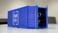
Smart meter. Image used courtesy of Power Integrations
Each switching controller (66 kHz nominal switching frequency) features an integrated 750 V or 900 V MOSFET to regulate power to the transformer primary and a synchronous rectification (SR) FET driver at the output for improved efficiency.
Along with its compact design, the LinkSwitch-XT2SR achieves up to 90% conversion efficiency while consuming less than 5 mW of no-load power, a key performance criterion to meet appliance energy conservation standards.
Power Integrations recently released several design example reports exploring the capabilities of the LinkSwitch-XT2SR.
12 W Dual-Output Power Supply
The LNK3773D from the LinkSwitch-XT2S family can be used to construct a 12 W supply that generates dual 12 V and 5 V output rails from a nominal 90-265 VAC input. The two outputs can deliver 420 mA and 1.4 A of load current, respectively.

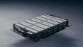
LinkSwitch-XT2SR. Image used courtesy of Power Integrations
In the design, the primary side of the transformer is connected to the rectified DC bus (from the AC input) and the controller’s internal 750 V MOSFET. The LNK3773D is self-starting and has an internal current source that charges the power bypass pin (BP) when AC power is applied to the input. The IC begins switching once the drain voltage of the internal MOSFET reaches 50 V.
On the secondary side of the supply, the flyback controller monitors the voltage at both outputs through resistor divider networks, switching the power MOSFET as needed to maintain the regulated outputs. The controller also drives the output SR FET (Q1) used on the 5 V output for better efficiency. The controller ensures that the power MOSFET is never on at the same time as the SR FET.
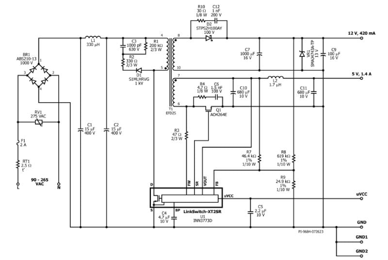
12 W dual output supply reference design. Image used courtesy of Power Integrations
Low ESR capacitors and an inductor filter out the switching frequencies to minimize output ripple. The supply’s 12 V output uses diode rectification and a similar R-C filtering circuit for ripple and noise suppression.
The uVCC pin provides regulated power for a system microcontroller without the need for an external regulator.
BOM and Non-Isolated Transformer Construction
The bill of materials (BOM) for the reference design consists of just 33 components and includes a material list and directions for constructing the dual output, non-isolated transformer. As a non-isolated topology, the primary role of the transformer is power signal conditioning, not system isolation.

Transformer electrical diagram. Image used courtesy of Power Integrations
The specified core for the transformer is EFD25, N87, or equivalent, gapped. The bobbin is EFD25-H-10-Pins, YingChin. The primary and two secondary windings use #29 AWG double-coated, #23 AWG double-coated, and #22 AWG triple-insulated wires.

Constructing the transformer. Image used courtesy of Power Integrations
Supply Performance
In testing, the supply reference design could reach 88% conversion efficiency operating at room temperature with full load on both outputs and an AC input of 150 VRMS.
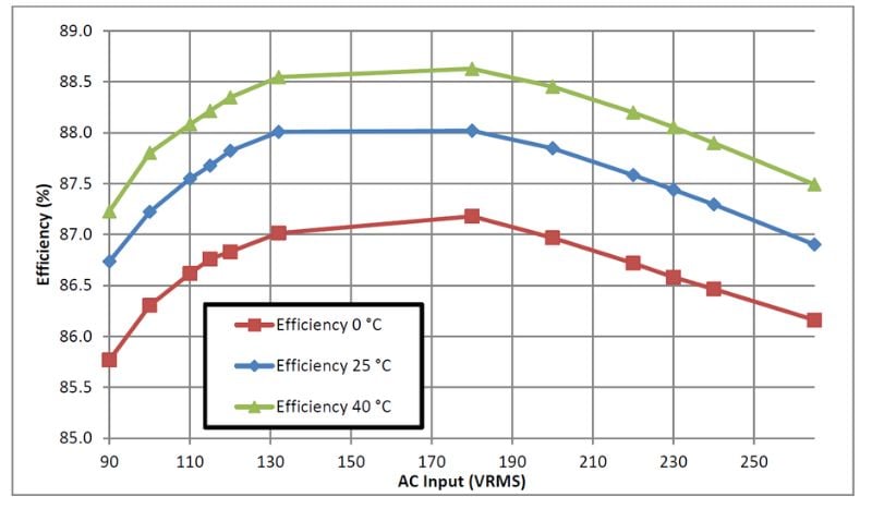
Supply reference design efficiency performance. Image used courtesy of Power Integrations
For the 5 V output, load regulation is less than 2% from zero to full load conditions.