Facebook
 Google
 GitHub
 Linkedin
Pushing Hall Effect Technology to New Limits
This article discusses how to use LEM uses Hall Effect Technology to manage fluxgate and improve efficiency, productivity and performance in many areas.
Reducing energy consumption and improving efficiency are key targets for most power electronics applications, especially in motor control drives, in uninterruptible and switch-mode power supplies or for industrial uses such as welding. Outside the industrial sphere, the same goals can be found in modern electricity generation plants using wind and solar energy.
To meet these requirements, it is necessary to use the most advanced materials, to improve insulation and to achieve better partial discharge levels to guarantee safety and immunity from external electrical, magnetic and electromagnetic fields. As well as EMC protection and low emissions, the aim is to maintain performance over a wide temperature range.
Achieving these with power semiconductors means searching for characteristics such as low thermal drift, fast response times, low influence in common mode, large bandwidth and low noise in the components around them. One company pushing these with transducers is LEM, and its latest products have gone beyond what were previously thought of as the limits of Hall effect technology.
Next step
Classical Hall effect technology has been used in the industrial market for a long time. While the accuracy is quite good at 1 or 2%, this has been offset by a poor performance over a wide temperature range. One possibility is to use instead of the Hall effect chip a fluxgate detector, which does improve stability over temperature. The Fluxgate detector is basically little more than a copper winding, however, managing its performance can be costly.

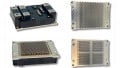
Figure 1: New LF xx10 current transducers range
Engineers at LEM, therefore, set about finding a way to make Hall effect technology achieve the sort of performance that fluxgate could manage. The result was an ASIC based on Hall effect technology for use in closed-loop mode. It also overcame other drawbacks with fluxgate such as noise, starting up with primary current and restarting without delay after an overload. This ASIC is at the heart of LEM’s latest transducers and is the largest contributor to improved performances in areas such as offset and offset drift. The secret behind the improvement is a patented spinning technique and specialist IC.
Such was the success that the company decided to renew its entire range of closed-loop Hall-effect based current transducers for nominal current measurements from 200 to 2000A. As such it has introduced four new series – the LF 210-S, LF 310-S, LF 510-S and, LF 1010-S with a fifth, the LF 2010-S, coming out in February 2015, see Figure 1.
Another important advantage of the LF xx10 family is its low sensitivity to external AC and DC fields, thus allowing a more compact design as it is not affected by fields created by other components that are close by. A higher measuring range is also provided even with a low di/dt value. This is due to the transformer creating a secondary current that is higher than the specified measuring range because it uses a magnetic core with a partial air gap.
This range should be of particular interest to R&D engineers in the industrial and rail transportation markets. They can help on measuring inverter output current, particularly for static converters. And they can be used in harsh environments. They are also fully compatible with the previous LEM LF xx05 range and fit in the same footprint, so they can be retrofitted into older installations.
Working principle
For accurate measurement of DC currents, the technology compensates the current linkage θP created by the current IP to be measured by an opposing current linkage θS created by a current IS flowing through a known number of turns NS (Figure 2) to obtain:

Figure 2: Closed-loop current transducer principle
with NP the number of primary turns and NS the number of secondary turns.
To obtain accurate measurement, it is necessary to have a highly accurate device to measure the condition © = 0 precisely. The aim is to obtain current transducers with the following characteristics:
- Excellent linearity;
- Outstanding long-term stability;
- Low residual noise;
- Low thermal drifts;
- High-frequency response; and
- High reliability
To achieve accurate compensation of the two opposing current linkages (©P and ©S), a detector capable of accurately measuring © = 0 must be used, which means the detector must be very sensitive to small values of a residual magnetic flux W (created by the current linkage ©) to achieve the greatest possible detector output signal.
Using this operating principle associated with the new LEM designed patented Hall effect ASIC previously mentioned, the LF xx10 current transducers cover nominal current measurements from 200 to 2000A (4000A peak). To operate, they only need a standard DC power supply range of ±11.4 to ±25.2V.
The transducers maintain all the advantages of the previous range while bringing improvements in accuracy, external field sensitivity, measuring range, common mode and EMC.
Characteristics
Overall accuracy is within ±0.3% of IPN at room temperature but just as important it is better than ±0.6 % of IPN over its entire operating temperature range from -40 to +85˚C, see Figure 3a.

Figure 3a: Typical overall accuracy of LF 1010 model over -40 to +85˚C

Figure 3b: Performance comparison between LF xx10 series and the previous generation of transducers
For the LF 1010 family, the initial offset at +25˚C is ±1A.turn with a maximum possible drift of ±1A.turn over the operating temperature range. Sensitivity error at +25˚C is ±0.1% and linearity is only ±0.1%. Measuring range has been improved to reach higher peak currents than with the LF xx5 series. With a 5000 turns ratio, the LF 1010 can measure up to 2500A peak whereas the LF 1005 was limited to 1800A peak.
Thanks to the partial air gap of the magnetic core (see Figure 4), the LF 510, 1010 and 2010 models have a very low sensitivity to external AC and DC fields. This allows a more compact design as there is practically no sensitivity to high current conductors near to the transducer.

Figure 4: Partial air gap on magnetic core
To simulate external fields, the best test is to place a busbar with nominal current at different positions close to the transducer, around. The added error due to the field created by this bar can be measured. This is also a way to simulate a return busbar and its effect on the accuracy of the transducer.

Figure 5a: Error created by a busbar close to the LF 1010 in front of the air gap (850ARMS 50Hz)

Figure 5b: Error created by a busbar close to the LF 1010 in front of the air gap (1000A DC)
For example, the sensitivity against AC or DC fields (worst case) with the LF 1010-S model is five times better than with the LF 1005-S (former generation). The typical error with an LF 1010-S is 2% of IPN compared with 10% with an LF 1005-S when submitted to the same conditions caused by AC or DC perturbating fields.
On response time (see Figure 6), the LF xx10 transducers have a typical delay (defined at 90% of IPN) against a current step at IPN of less than 0.5µs. The magnetic core with a partial air gap improves the magnetic coupling, and so, improves the response against di/dt.

Figure 6: LF 1010 response time at 90% of IPN


Figure 7: LF 1010-S noise level
The bandwidth is only limited by the resonance frequency of the secondary winding to roughly 100 kHz. This resonance is due to the leakage inductance and the parasitic capacitors between winding layers and between turns.
Signal-to-noise ratio (SNR) compares the level of a desired signal to the level of background noise. It is defined as the ratio of signal power to the noise power, often expressed in decibels. When a measurement is digitised, the number of bits used to represent the measurement determines the maximum possible signal-to-noise ratio. Thanks to the very good SNR, the LF xx10 models have more than 14bit resolution, see Figure 7.
Various connections are available for the secondary side, such as connectors, cables, terminals and threaded studs according to the customer’s specifications, and a mounting kit for the primary bar will be available on LF 2010 models.
As semiconductor commutations are faster, a higher dv/dt between primary (high potential) and secondary (low potential) sides of the transducers is seen. The secondary side is generally connected to ground for safety reasons. The primary side is under some differential voltages, but the voltage can float. The potential can then change on the primary side to cause some perturbations at the secondary (output) of the transducer. This cannot be filtered because it would degrade the response time and frequency performances, so the parasitic capacitance between the primary and secondary sides of the transducer has to be reduced during its design to the lowest possible. Having a low parasitic capacitance between the primary conductor and the secondary side of the transducer is a way to reduce the effect of dynamic common mode. And if this is not enough, an electrostatic screen can be added to cancel common-mode perturbations.
The LF xx10 models have been designed and tested according to the latest recognised worldwide standards for industry and traction applications. These include EN 50178 for electronic equipment used in power installations in industrial applications and EN 50155 for electronic equipment used on rolling stock in railway applications. These standards guarantee the overall performances of products in industry and railway environments.
The LF xx10 transducers are UL recognised and CE marked as a guarantee of compliance to the European EMC directive 2004/108/ EEC and low voltage directive 2006/95/EEC. They also comply with the derived local EMC regulations and with the EN 50121-3-2 standard (railway EMC standard) in its latest update, with EMC constraints higher than that of the typical industrial application standards.
Conclusion
Systems integrate more and more sensors due to the high levels of automation that improve productivity and energy efficiency. Whatever kinds of sensors, current transducers can be used to make the link between different systems for monitoring and control. These systems, in the search for the best efficiency, can benefit from the performance of the new LF xx10 series.
These transducers are suitable for any kind of rugged environments where good performance is required in terms of accuracy, gain, linearity, low initial offset and low thermal drift. Featuring high immunity to external interferences generated by adjacent currents or external perturbations, the LF xx10 transducers provide excellent reliability.
About the Author
Michel Ghilardi works as the R&D Programme Manager at LEM, a market leader in providing innovative and high-quality solutions for measuring electrical parameters. Its core products - current and voltage transducers - are used in a broad range of applications in drives & welding, renewable energies & power supplies, traction, high precision, conventional and green cars businesses.
This. article originally appeared in the Bodo’s Power Systems magazine.
Related Content