Facebook
 Google
 GitHub
 Linkedin
Monitoring DC/AC Current in Locations Where Other Current Sensors Cannot
Electrification of Road, Off-road, Marine, and Air vehicles; development of Renewable Energy Electrical Sources, and Energy Storage; monitoring and improving the efficiency of existing Electrical Grid, Transit, and Industrial Installations, can benefit from electrically isolated Current Transducers for condition monitoring and fault diagnosis.
Fixed aperture magnetic core based Current Transducers provide dc and ac response with excellent accuracy but they are often difficult to install on existing systems. Split Current Transducers are typically designed for hand-held measurements by an operator rather than semi- or permanent installation and are not suitable for operation over a wide temperature range, in moist, dirty or high vibration environments or where high fault current overloads are possible. Generally the Transducer apertures are limited and inadequate for high current, large cross-section cables or bus bars.
Rogowski Coil based current transducers can be designed for very high peak current and with long, small cross-section Coils to enclose almost any current conductor and for operation in harsh environments. But the Rogowski Coil response is proportional to frequency so the response does not extend to dc and the S/N degrades at low frequency.
GMW has developed a range of Current Transducers using an array of magnetic sensors to measure the magnetic field generated by the enclosed electrical current. This approach is particularly suitable for the measurement of high dc and ac current with frequency response up to about 75kHz (-3dB). There is no magnetic core and thus no magnetic hysteresis effects or damage from pulse or continuous high current overload. The Transducer cross-section is small, and unlike a magnetic cored transducer, independent of the current rating. The Transducer aperture geometry can be designed to match specific cross-section current conductors with large apertures. For the measurement of high peak and/or high di/dt currents with a dc component a GMW Coreless Current Transducer can be co-located with a Rogowski Coil in a compact combination with no interaction between the two.
Ampere’s Circuital Law:
Magnetic core or Rogowski Coil current transducers that provide an output signal accurately proportional to the enclosed current for frequencies from dc to over 2GHz are implementations of Ampere’s Circuital Law as summarized in Figure 1.

Figure 1. Ampere’s Circuital Law. Image used courtesy of Bodo’s Power Systems
Approximating Ampere’s Circuital Law:
The GMW Current Probes utilize an array of “point” magnetic field sensors that can enclose the current to be measured. The Ampere’s Line Integral can be approximated by a summation of magnetic field measurements made at points around the current, see Figure 2.

Figure 2. Summation Approximation to Ampere’s Circuital Law. Image used courtesy of Bodo’s Power Systems
Different Probe Geometries:
Ampere’s Law applies to any closed curve and thus the geometry of the Coreless Current Sensor can be tailored to the shape and dimensions of the primary conductor and associated insulation. Geometries GMW has developed include:
CPC Current Probe Clip:
Current Ranges: +/250A to +/-2000A. Output Signal: 0 +/-2V. Sensitivity Accuracy, +/-1%. Aperture: 27mm circular. Mass: 30g (1oz). Operating Temperature: -40C to +100C. Dust & Moisture: Sealed IP65, EN60529. Power: +5V, <85mA (USB Port).

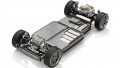
Figure 3. The very small size of the CPC Current Probe Clip enables it to be used in parallel with a Rogowski Coil to measure dc and low frequency current components on a vehicle charging cable without disconnection of any cables. Courtesy Argonne National Laboratory, Ted Bohn. Image used courtesy of Bodo’s Power Systems
CPCO Current Probe, Clamp-On:
Current Ranges: +/0.5kA to +/-16kA. Output Signal: Voltage or Current. Sensitivity Accuracy, +/-1%. Aperture: 77mm or 160mm circular. Mass: 120g or 300g. Operating Temperature: -40C to +85C. Dust & Moisture: Sealed IP65, EN60529. Power: +11V to 31V, <0.8W.
CCS Coreless Current Sensor, Slip-On:
Current Ranges: +/0.5kA to +/-12kA. Output Signal:0 +/-2V. Sensitivity Accuracy, +/-1%. Aperture: U-shape, 30mm wide x 90mm deep. Mass: 65g. Operating Temperature: -40C to +85C. Dust & Moisture: Sealed IP65, EN60529. Power: +5V, <150mA.
No Artifacts or Damage from any Primary Current Overload:
During an overload primary current the Magnetic Sensors of the Probe electrically limit and the Probe Signal output electrically limits at about 1.25 time the nominal range with no overshoot, sagging, ringing or damage from any continuous overload current.

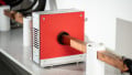
Figure 4. Four CPCO Clamp-On, 160mm aperture, 12kA Current Probes used to monitor bus bar current in an electrochemical application with reliable operation in a harsh environment. Image used courtesy of Bodo’s Power Systems
Within less than 10us of the primary current being within range the output signal follows the primary current with no baseline shift. This enables the current range of a Coreless Current Sensor to be selected for optimum signal to noise for the normal operation currents even though there may be very high fault current peaks.

Figure 5. Hand Current Probe Assembly with Slip-On CSS, Insulating Handle and Data Logger for monitoring Bus Bar or Cable Current. Image used courtesy of Bodo’s Power Systems
Current Probe Rejection of External Magnetic Fields:
The Summation Approximation to Ampere’s Law provides high rejection of external magnetic fields arising from nearby currents or magnetic materials.
Signal Stability after Repeated Thermal Cycling:
Different Models of CPC Current Probe Clip and CPCO Current Probe Clamp-On have been exposed to 50 thermal cycles between -40C and +85C and the maximum changes observed are: Zero Offset, +/-0.4% of full-scale; Sensitivity, +/- 0.5%.

Figure 6a. The Output Signal from a CPC Current Probe Clip with nominal range of +/-250A operating with a 750Arms, +/-1060A, 60Hz primary current. The Scope Sensitivity is 200A/division vertical and 10ms/ division horizontal. The green trace is the primary current measured with a Fluxgate Transducer, the yellow trace is the CPC 250A Current Probe signal showing the clean electrical limit with the same sign as the primary current and no artifacts. Image used courtesy of Bodo’s Power Systems

Figure 6b. The same measurement as Figure 6a with the vertical and horizontal sensitivities increased to show that there is negligible baseline and phase shift after a high current overload. Image used courtesy of Bodo’s Power Systems

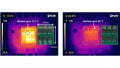
Figure 7. The Zero Offset change of a CPCO with 77mm aperture and +/-4kA range arising from a 1kA dc current at 25mm from the CPCO surface. Image used courtesy of Bodo’s Power Systems
Low Signal noise down to dc:
The output signal noise of the Coreless Probes has no switching frequency peaks and is repeatable from Probe to Probe enabling continuous spectral analysis of the current to monitor for mechanical damage, vibration, insulation degradation or load changes. DC or low frequency current components can be monitored with high resolution on nominally ac primary current for protection of high efficiency ac power transformers.

Figure 8. Temperature Cycle of CPC Current Probe Clip and CPCO current Probe Clamp-On to measure Zero Offset and Sensitivity Stability. Image used courtesy of Bodo’s Power Systems

Figure 9. The noise spectrum of a CPCO with 77 mm aperture and +/-4 kA range with a primary current of about 0.15Arms at 21Hz. The primary current is clearly resolved. Image used courtesy of Bodo’s Power Systems
Conclusion
GMW Coreless Current Sensors with Clamp-On, Clip-On or Slip-On geometry and large apertures can provide isolated and continuous monitoring of high currents without disconnection of existing conductors in locations with restricted space and high magnetic fields from nearby currents or transformers. Accurate amplitude and phase response with low noise from dc to over 40kHz(-3dB) enables power and spectrum condition monitoring of electrical systems even in harsh environments with wide temperature variations, moisture, dust and mechanical vibration.
This article, written by Lou Law and Ian Walker, originally appeared in Bodo’s Power Systems magazine