 Facebook
 Google
 GitHub
 Linkedin
What is a Ćuk Converter?
This article explains the topology and uses of a Ćuk converter, which emulates ideal transformer behavior by offering pure DC input and output currents with almost no ripple.
A power converter that converts a source of direct current (DC) from one voltage level to another is called a DC-DC converter. These converters find applications in a wide range of systems including renewable energy integration with storage, medical devices, and power transmission. Each of these scenarios demands specific voltage levels and means of power conversion. This has led to several types of DC-DC converters.
The buck-boost converter is one of the most sought after types because of its ability to step-up or step-down at different time instants based on the requirement. Read on to learn more about a specific variant of buck-boost topology called the Ćuk converter that magically yields zero-ripple current.
The Ćuk Converter Topology
The Ćuk converter is named after its inventor, Slobodan Ćuk. It was noted as a new switching device that was synthesized using the least number of storage and switching elements. It emulates the ideal transformer behavior by offering pure DC input and output currents with almost no ripple.

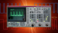
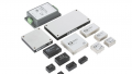
Figure 1. The LM2611 Ćuk converter from Texas Instruments.
The motivation behind this invention was to reduce or eliminate the formidable pulsating currents while the envisioned objective was to synthesize the generalized DC-DC transformer function with ideal current waveforms.
After the invention of the Ćuk converter, the concept of coupling inductances in switching converters grew more popular. This paved the way for the investigation of integrated magnetic structures that promise a further reduction in size, weight, and magnetic losses. Thus, it is described as a culmination of research in two parallel lines — practical use cases that enable the synthesis of multiple useful converter configurations, and theoretical use cases which deal with new concepts that can be extended to several switching structures [1].
How is the Ćuk Converter Topology Unique?
Based on the interconnection of several buck and boost converters in cascade or cascode form, variants like Ćuk, SEPIC, and Zeta converters are derived. A Ćuk converter, also known as optimum topology converter, is essentially a boost converter followed by a buck converter, but they share the same switching device. It is key to note that the output capacitor of the boost converter functions as the energy source for the buck converter.
The Ćuk converter can be incorporated to yield either voltage step-up or step-down, thus making it a top choice for a wide range of voltage requirements. Also, it uses a capacitor as the key energy storage component whereas most of the other power converters employ inductors for that purpose.
The converter design is such that the current flowing through the input side is always continuous irrespective of the state of the switch. The circuit in Figure 2 shows a Ćuk converter circuit and it is evident that LC filters are formed both at the input and output which facilitates smooth current waveforms. This also aids in achieving a very low output voltage ripple as a second-order low pass filter is formed by the combination of inductors and capacitors.

Figure 2. Circuit diagram of the Ćuk converter
In addition, the design of inductors ensures zero-ripple behavior. Since the currents are non-pulsating, electromagnetic interference (EMI) can be significantly reduced by incorporating this topology. Thus, it also leads to inherently lower noise and higher overall efficiency.
How Does a Ćuk Converter Work?
The topology of a Ćuk converter involves a low-side switch, diode, inductors, and a coupling capacitor between the input and output terminals. In the conventional topology, the inductors are typically uncoupled. Few variants of the basic topology incorporate coupled inductors instead that are typically matched in value. In some other cases, the coupled inductors are integrated with a transformer that additionally offers enhanced step-up, volume reduction, and isolation features.
It is evident that the converter has two inductor currents and two capacitor voltages that need to be determined. The strategy employed for circuit analysis can be summed up as the application of a volt-second balance for each inductor voltage and charge balance for each capacitor current [2]. Simplification is carried out using small ripple approximation and the resulting four equations are solved to obtain the values for the four unknowns.
From Figure 3, it can be observed that when the switch is conducting, the diode is off and the capacitor C1 releases energy to the output.

Figure 3. Analysis of the Ćuk converter circuit behavior
Along those same lines, when the switch is off, the diode is conducting and capacitor C1 is charged from the input.
Applications: Key Areas Where Ćuk Converters are Valuable
Due to the uniqueness of the Ćuk converter topology and its variants, they are employed in very specific and crucial applications. In general, they can be utilized when the magnitude of the output voltage requirement is greater or lesser than the input voltage. However, they are ideal for high voltage, negative polarity output voltage, and low standby continuous current applications.
They find extensive applications in renewable energy integration. This mainly includes systems with solar panels on the input side and hybrid solar-wind energy systems. They are deemed ideal for photovoltaic applications as they facilitate regulation and operation at the maximum power point (MPP). Ćuk converters are also used in conjunction with batteries on the low voltage DC supply side in electric vehicles.
Key References
S. Ćuk, "A new zero-ripple switching DC-to-DC converter and integrated magnetics," in IEEE Transactions on Magnetics, vol. 19, no. 2, pp. 57-75, March 1983, DOI: 10.1109/TMAG.1983.1062238.
Robert W Erickson and Dragan Maksimovic, Fundamentals of power electronics, Springer Science & Business Media, 2007.


Your Figure 2 ckt diagram is wrong! The Cuk converter has a negative (inverted) output for the non-isolated type. This is a big deal since polarity matters. I suggest you fix it.