Facebook
 Google
 GitHub
 Linkedin
Vincotech’s New On-Line Simulator Launches from a Webpage
With no download necessary, the new simulation tool requires no third-party software and works with any operating system.
Vincotech describes it’s VINcoSIM as “the first simulator to launch from a webpage.” This powerful tool will make it easy for designers to learn exactly how a Vincotech module will behave in the real world without investing a dime or a minute in hardware.

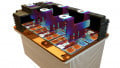
The VINcoSIM simulation tool. Image courtesy of Vincotech
A group company of Mitsubishi, Vincotech designs and builds power modules for a broad range of applications, and VINcoSIM will make it easy to find the right power device for specific use cases.
Building on Vincotech’s 20-year history in ISE simulation, the VINcoSIM offers designers the latest in topology modeling, serving as an accurate power loss and temperature calculation engine. With this powerful tool, users can actually define custom heatsink builds and do it in a one-step configuration. Designers will be able to easily assess their options and to opt for the best fit.
Making Well Informed Decisions
As noted by Vincotech CEO Eckart Seitter, “This tool is a great leap forward.” He goes on to say that, “As a reliable partner, we aim to bring speed and flexibility to our business relationships. Part of that is helping customers make fast but well-informed decisions. We have always gone to great lengths to provide accurate, reliable simulation tools. And VINcoSIM is our most powerful and convenient power module selection tool yet.”
Using VINcoSIM
VINcoSIM is designed to fast-track simulation, and every Vincotech module, along with every topology, can be simulated under an array of conditions. When the user selects a Vincotech device from the website, configuration occurs automatically. Designed to simulate any topology, the simulator employs substantiated data from actual laboratory measurements.
The simple user interface allows for all specifications to be submitted in one single configuration step. The results of the simulation is available to users in seconds. Critically, the simulator lets the designer know the type of thermal interface material is assumed during characterization.
The Simulation Setup
In an example illustrated in a VINcoTECH video, we select a given VINcoTECH power module, and the simulator divides it into its elements, in this case, the rectifier, the brake chopper and the inverter.

Simulation setup. Image courtesy of VINcoTECH video (1:28)
Each element has its own input and output parameters, and they work independently from each other. The illustration above shows where the input and output voltage is referenced, along with the current. Then the control values, which define how to the component is driven, are set by the user.
Running the Simulation
With the setup complete, the user presses the “RUN SIMULATION” button to trigger the VINcoTECH simulation core. Once the simulation successfully converts, a summary is generated, illustrating each of the given power module’s elements.

Simulation setup. Image courtesy of VINcoTECH video (2:21)
Here, we see the highest temperature for each junction, power losses, and overall efficiency. At the very top, the apparent output power, total module power efficiency, and the total power losses are listed. The user can also cause the generation of a pdf file that contains all settings and results.
More Details
The user can choose which component is to be individually outlined. Performances of the chosen components are outlined, with guidance on each component’s power losses and temperature swings. Graphical depictions on each component’s voltages and currents are also available. As before, these results, too, can download in a file for the designer’s use.