Facebook
 Google
 GitHub
 Linkedin
Understanding Three-Wire Control
Three-wire control of a 3-phase AC motor by means of a 3-phase (3-pole) electromagnetic motor starter uses momentary switches with either pushbutton- or selector-type operators.
Two-wire control of one or more 3-phase AC motors, which uses maintain-type pushbutton or selector switches, is normally limited to just ON/OFF control. 3-wire control is normally employed when time delay between starting and stopping, when an orderly sequence of motors being either started or stopped or when some other form of interlock is required. Three-wire control of a 3-phase AC motor by means of a 3-phase (3-pole) electromagnetic motor starter uses momentary switches with either pushbutton- or selector-type operators. The pushbutton (PB) is the more common option.
Momentary Switches are Required
Two momentary switches are required for the 3-wire control of the motor starter solenoid coil: As shown in Figure 1, one momentary switch must be in an NC configuration at rest, and the other one must be in a NO configuration at rest. The two switches are wired in series with continuous control power normally applied to the NC Stop PB switch. The NO Start PB switch is supplied through (in series with) the NC Stop PB switch.
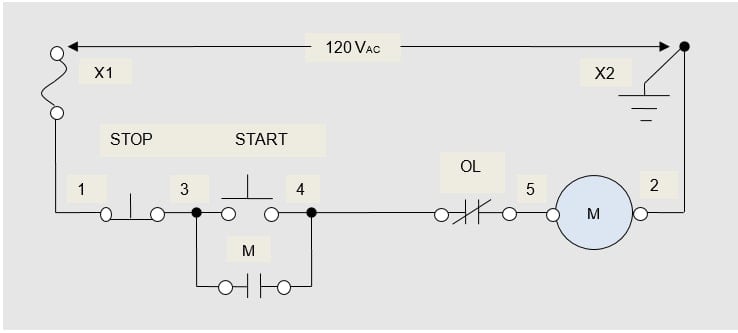
Figure 1. Three-wire control of a 3-phase AC motor with a 3-pole electromagnetic motor starter.
The two series PB switches in the 3-wire control of a 3-phase AC motor (Figure 1) replace the single selector switch contacts in the 2-wire control of the 3-phase AC motor. The NO Start PB switch serves to initiate (start or turn on) a control function. When the NO Start PB switch is pushed closed (or activated), power is applied to the 3-pole electromagnetic motor-starter solenoid coil. The solenoid, in turn, applies power to the AC motor. Because this is a momentary switch when it is released, the starter is de-energized, and the motor stops.

Figure 2. The two series PB switches in the 3-wire control of a 3-phase AC motor replace the single selector switch contacts in the 2-wire control arrangement.
A Seal-In Circuit is required
To keep the 3-phase AC motor in a run status when the momentary NO Start PB switch is released, a seal-in circuit is required. A seal-in circuit consists of a set of NO auxiliary contacts on the 3-pole electromagnetic motor-starter power contactor (NO contact identified as M in Figure 1) that will create an additional path in parallel with the NO Start PB switch contacts when closed. When the NO auxiliary contact M closes due to the M solenoid being energized by the start PB (when initially pressed), the NO Start PB switch can be released, and control power to the solenoid coil will be maintained through this seal-In contact “M.” The use of the seal-in circuit is referred to as auxiliary interlock. The auxiliary seal-in circuit is also referred to as the hold-in circuit, the memory circuit, or the maintaining circuit.
Control Sequence
The NC momentary PB switch in Figure 1 serves to interrupt (stop or turn off) the control function. If the electric motor is in a run condition, the motor-starter solenoid will drop out (be de-energized or de-activated), and the motor will stop when the NC stop PB is opened. A run condition means that the NO Start PB switch was momentarily closed, and now the held-closed seal-in circuit is applying continuous power to the 3-pole electromagnetic motor-starter solenoid coil and the NC Stop PB switch is closed. When the NC Stop PB switch is pressed, power is removed from the solenoid coil of the M motor starter. Now when released, it then returns to its normally closed position. The 3-phase AC motor will remain stopped. It remains stopped because both conductive paths (the NO Start PB switch contacts and the NO motor-starter auxiliary contacts) between the load side of the NC Stop PB switch and the line side of the three-pole electromagnetic motor-starter solenoid coil (the NO Start PB switch contacts and the NO motor-starter auxiliary contacts) are in their normally-open (NO) at-rest position. For the motor to be re-started, the NO Start PB switch will need to be activated (closed) again.
If the NC Stop PB switch is held open (depressed), activating (closing) the NO Start PB switch will not initiate the control function: the circuit is disabled. This method of control lockout is referred to as locked-stop switching. It is often used to prevent a 3-phase AC motor from being started during a process cycle.
Where the Name Came From
As with 2-wire control, 3-wire control also gets its name from the number of wires that must be extended from the 3-pole electromagnetic motor-starter enclosure (where the control power originates) to the remote operator’s control station. In the drawing of the schematic and in the actual wiring of the 3-wire control of a single 3-phase AC motor, one wire supplies the series switches with fused, continuous power. It is normally connected to the line side of the NC Stop PB switch.
The second wire, extended from one side of the NO auxiliary contacts on the 3-pole electromagnetic motor-starter power contactor, is connected to the midpoint or interconnection of the two PB switches. The third wire, which is the switch-leg conductor used to start the 3-phase AC motor, is connected to the load side of both the NO auxiliary contacts on the motor starter and the NO Start PB switch contacts. The installation of these second and third control wires places these two sets of NO contacts in parallel.
On the 3-pole electromagnetic motor starter, the third wire connects the load side of the paralleled NO Start PB switch and the NO auxiliary contacts on the motor-starter power contactor to the line side of the NC overload-relay control contacts OL. The load side terminal of the NC motor-starter overload-relay control contacts is wired series-connected to the line side terminal of the motor-starter solenoid coil. The other side or terminal of the motor-starter solenoid coil is referred to as the common side because it is connected directly to wire #2: the grounded conductor or common-return of the control circuit.
If the control-circuit power is not referenced to the ground (the common or return side of the control circuit is not connected directly to the equipment-grounding system), the NC overload-relay control contacts can be wired after the 3-pole electromagnetic motor-starter solenoid coil wire terminal on its common side.
The power or load circuit wiring diagram for a single 3-phase AC motor using 3-wire control is the same as for the 2-wire control of the same motor.
Three‐wire control has three wires leading from the control device to a starter to complete the circuit. Auxiliary contacts are added to starters to give memory to three‐wire control circuits that use pushbuttons.
When a motor starter coil (M) is energized, the coil causes a normally open contact (NO) to close and remain closed (memory) until the coil is de‐energized. Memory is a control function that keeps a motor running after the start push button is released. Memory circuits are also known as holding or seal-in circuits. When a memory circuit is ON, the circuit remains ON until turned OFF and remains OFF until the circuit is turned back ON.