Facebook
 Google
 GitHub
 Linkedin
The World’s First Peak Current Load SMD Ferrite: The Multilayer Power Suppression Bead
This article introduces the Würth Elektronik eiSos' Multilayer Power Suppression Bead (MPSB) and discusses its advantages and benefits.
A Chip Bead Ferrite has inductance that is established using a screen printing process. This is optimised for as high as possible losses for use as filter. Therefore, it consists of a nickel-zinc-ferrite mixture and a very fine superimposed inner silver layer with thickness of a few micrometres. This structure makes the classic SMD ferrite more vulnerable for current spikes above the maximum rated current load and in special cases results in degenerative or also immediate destruction of the component.
A typical application is shown in Figure 1. The multilayer ferrite is used as longitudinal filter at the input of the circuit. Due to the low on-resistance of the capacitor, a very high pulse current flows for a short time at switch-on. This pulse current temporarily loads the SMD ferrite with a multiple of the current that is many times above the maximum specified rated current.
In this example, the optimized multilayer ferrite, that is designated by Würth Elektronik eiSos as Multilayer Power Suppression Bead (MPSB), has an impedance of 600 ohms for a maximum permissible rated current load of 2.1 A. The one-time current peak in this constellation has a peak value of approx. 19 A and has an overall pulse length of 0.8 ms until it has been reduced to the rated current of the circuit.
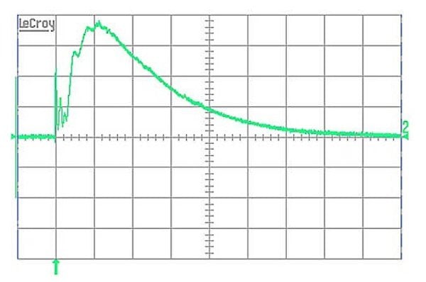

Figure 1: Application with peak current at switch-on (5 A / DIV | 100 µs / DIV)
It generally applies for the SMD ferrites that the maximum rated current also defines the maximum current amplitude for temporary load. However, using the new WE-MPSB series with pulse load, multilayer ferrites are now available that consider the peak current in the datasheet.
Background of the application
Current peaks occur frequently, for example at switch-on of diverse switch mode power supplies and for electric motors. Known applications with recurring pulses are, for example, windscreen wiper motors in vehicles. But also ballasts of luminaires can produce a high current peak at switch-on of the light. In particular, the input capacitor in a switch-mode power supply can produce a high peak current that the upstream EMC filter must withstand. Pulses in this context are understood as temporary current peaks with a time limitation less than 8 ms until complete reduction to the DC current of the circuit.
The appropriate approach in the search for a common standard for the measurement of pulse load capacity for SMD ferrites has been found in the definition of the melting integral for fuses. A pulse of 8 ms duration, according to the standard, is applied to the fuse to “give the current time” to heat the fuse for the determination of the I²t value of the fuses. If the fuse withstands this, the current is increased until the increase results in destruction of the fuse. In doing so, a pause of 10 s between the pulses is required to give the component the necessary time for regeneration (cooling down). Würth Elektronik eiSos has developed an adapted test routine based on this fuse standard for the multilayer ferrites. Based on the 8 ms pulse, current with increasing pulses is applied to the multilayer ferrite until destruction. The components are loaded with iteratively increasing pulse currents starting from 1 A. The pulse rectangle shown in Figure 2 was selected as pulse shape for all tests as this loads the component with the highest possible energy for the pulse duration ʅ although it will only very rarely be applicable in practice at switch on.

Figure 2: Possible pulse shapes at switch-on
Pulse Strength
In comparison with the fuse, it is not possible for the multilayer SMD ferrite to specify any generally applicable formula with which conclusions can be drawn about the various current peaks for different pulse lengths using the calculation of the melt integral. The empirically determined datasheet values can be traced back to long term test series with different parameters.
The following shows an example for clarification of the non-applicability of the melt integral for the multilayer ferrites using the example of the article 742 792 206 01 (Z = 600 Ω, IR = 2.1 A, RDC,typ = 43 mΩ).
The WE-MPSB has maximum peak current load capability of 18 A with a pulse length of 8 ms. This produces an I²t value of 2.592 A²ms (18 A @ 8 ms (5-sec pause, 24 °C) I²t = 2.592 A²s).
The following result is obtained if the current for a pulse length of 2ms based on the I²t value for 8 ms is calculated:
However, the datasheet value shown in Figure 3 is specified as max. 24 A.
The calculated I²t value deviates significantly from the measured values. Consequently, due to this different behaviour of the SMD ferrite from the fuse, it is not possible to apply the known calculation of the melt integral I²t to a multilayer ferrite.

Figure 3: Specified peak current load capability

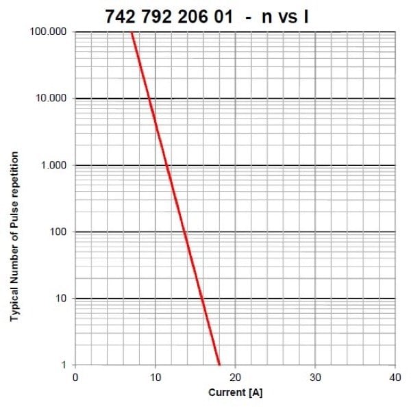
Figure 4: Display of the current as dependence on pulse length and the number of pulses
Optimisations for the WE - MPSB
Due to its silver layers with a thickness of only 8 - 20 µm, the multilayer ferrite is not constructively designed for high pulse currents. Würth Elektronik eiSos has developed a new, optimized design with a perfect mixture of high currents, up to 75% smaller RDC and as high as possible impedance over the complete frequency spectrum. Depending on the impedance and current level, the optimum design is used individually for each article.
Definition of the pulse strength
The pulse strength is considered in more detail using the example of the article 742 792 206 01.
The current / pulse curve shown in Figure 5a shows the maximum permitted peak current for the respective tested pulse lengths. The tested range covers the time range of 0.5 ms to 8 ms pulse length. This curve is measured individually for each article and is only permissible for any consideration with one-time pulse.
The consideration of the permitted maximum pulse current visible in Figure 4b for a repeating pulse is possible using the second curve in the datasheet. This curve is a limit value consideration of the maximum peak current for repeating pulses. A maximum pulse length of 8 ms was selected for determination of the curve.
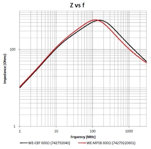

Figure 5: Comparison of the impedance and rated current load capability of the WE-CBF and WE-MPSB 600 Ω types
Tnt triangle influencing factors
The influencing factors are:
- The pulse lengths t that are tested as standard from 0.5 ms to 8 ms. The longer the pulse, the smaller is the maximum pulse load capability.
- The number of pulses that are tested from 10 to 100,000 pulses (see Figure 5b). The maximum permissible pulse load capability drops as the pulse frequency increases.
- The temperature should be noted as third reducing influencing factor; as the temperature increases, RDC increases which results in further reduction of the maximum pulse load.
Each of these interlinked systems is burdened with the dependency on the underlying pause between the individual pulses. In order to carry out an analysis of the linked system with a smaller pause time, it is necessary to measure the temperature [T], pulse repetitions [n] and pulse length [t] influencing factors again.
Comparison of the WE - MPSB with the WE - CBF series
The objective of the WE-MPSB Series is to achieve a comparable impedance as for the WE-CBF Series with additionally optimised resistance and load capability with pulse currents.
Using the example of the 600 Ω models in size 0805 shown in Figure 5, the WE-MPSB Series with almost the same impedance has a higher rated current due to the smaller resistance.
The WE-MPSB Series has significantly higher pulse load capability than a comparable WE-CBF Series model. Figure 6 shows the maximum pulse level of the 600 Ω model on the graph on the left and the maximum pulse level of the comparable WE-MPSB 600 Ω model on the graph on the right.
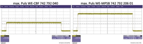
Figure 6: Comparison of the different pulse load capability of the WE-CBF and WE-MPSB series
Summary
The WE-MPSB Series has been developed based on the requirements of circuits that load the multilayer ferrites with temporary peak currents exceeding the rated current. The maximum pulse load capabilities of the multilayer ferrites have been determined by measurement using an in-house test routine that is different from that of the fuses. In comparison with existing multilayer structures, the layer structure has been optimised to generate higher current load capability using lower resistances. The WE-MPSB Series is thus ideally suitable for use in circuits with pulse currents.
About the Author
Markus Holzbrecher works as a Product Manager at Würth Elektronik eiSos since December 2010. He earned his Master's Degree (Diplom-Ingenieur) in Telecommunications / Communications Technology at Leipzig University of Applied Sciences (HTWK Leipzig).
This article originally appeared in the Bodo’s Power Systems magazine.