The Pros and Cons of Integrated Magnetics
This article analyzes the benefits and possible drawbacks integrated magnetics has to offer and the areas of application where utilizing integrated magnetics in a design is effective.
In a majority of switched-mode power electronics systems, inductors and transformers are the key contributors to the overall size, weight, and volume. In order to optimize such systems, magnetic integration is a solution where two or more magnetic elements are combined into a single structure.
It is imperative to consider proper phasing of windings and appropriate placement of the air gap so that core material can be considerably reduced [1]. We learned the concept of integrated magnetics, nuances of design, and how it serves as a building block for several power electronic systems in the previous articles. Come read on to analyze the benefits it has to offer and the areas of application where this is effective.
Benefits Analysis: Advantages and Disadvantages
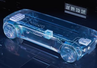
It is known that operating at a higher frequency like a few tens of kHz can lead to the use of lighter and more compact magnetic devices as compared to operation at line frequency. However, even in this case, the magnetic devices can account for about half of the size of the entire switching converter system. Thus, circuit designers are always looking collectively at the system components that can be optimized as in Figure 1 [2] and tend to focus on magnetics due to the following advantages.

Figure 1. System components under the review of the circuit designer
Increasing Operating Frequency
Increasing the operating frequency further can theoretically make the system smaller, but has its disadvantages. High operating frequency also translates to higher core losses and lower flux density. Thus, a better option would be to go with integrating multiple magnetic components into a single device essentially known as an integrated magnetics structure.
The integrated magnetics variant provides buck and boost capabilities along with inherent input and output current filtering. It reduces the internal energy storage, improves the dynamic performance, and facilitates desirable operation at relatively high frequency. The coupling of inductors reduces the overall size of the system along with the advantage of eliminating current ripple in one of the windings. Controlled coupling between the magnetic components helps facilitate specific functions [2].
Performance and Size Improvements
The use of an integrated magnetic structure promises performance improvement along with a reduction in size and weight. A central magnetic branch can be removed in this case due to zero total flux resulting from fluxes in the opposite direction. This translates to a smaller and lighter structure with comparatively lower core loss while maintaining the copper loss value and the energy storage capability. This further aids in efficiency improvement due to reduced core losses along with high-density systems, managing thermal issues, and managing space.
Also, if two cores are stacked together with the same number of turns wound on them, the value of inductance, core loss, and energy storage capability in them will be the same as that in a series configuration of two separate inductors. But there is a significant reduction in the length of the copper wire wound, leading to a reduction in weight and copper loss. This further improves the overall efficiency along with making the system compact.
Ripple steering technique, the ability to reduce the inductor ripple current to essentially zero, can be employed to reduce the size of the filter capacitor using the winding leakage inductance [3]. This further facilitates the use of gaps in the outer legs to achieve the ripple-free behavior. Electromagnetic interference (EMI) is reduced significantly as the shorter traces lead to a reduction in the amount of area that radiates leading to less antenna effect. Since the layout is more organized, the shield required is smaller. Also, the lower resistance in the shorter traces leads to reduced heat emission thus improving operational efficiency.
Applications Where Integrated Magnetics are Effective
In most of the forward topology converters, transformers are used for the transfer of energy and isolation while the inductors facilitate energy storage. Even though these elements perform different functions, they can still be integrated into a single structure either in a side-by-side or a top-to-bottom configuration. It is applicable for any power rating where size is critical, ideal with planar transformers, and design reconfiguration is not necessary as the platform is standardized. Typically, integrated magnetic structures are ideal for use in topologies within the range of 50 W to 200 W.
The other topologies that gracefully employ the integrated magnetic structure include basic converters like a modified buck converter for zero output ripple, boost derived converter, integrated magnetic isolated boost converter, forward converter, coupled-inductor quasi-square wave converter, and variants of conventional Ćuk converter.
Advanced topologies such as multi-output buck-derived quasi-square wave converters, push-pull version of integrated magnetic forward converters, single-ended Weinberg converters, Severns converters, Hughes converters, dual converters, and multi-mode converters also benefit from the integrated magnetic structure [4].
Key References
- Majid Dadafshar and John Gallagher, ‘Exploiting Integrated Planar Magnetics’, Power Electronics Magazine, 2005.
- Yim-Shu Lee, Leung-Pong Wong, and D. K. Cheng. “Simulation and design of integrated magnetics for power converters” in IEEE Transactions on Magnetics 39.2 (2003), pp. 1008–1018.
- S. S. Nag, S. Mishra, and A. Joshi. “A Passive Filter Building Block for Input or Output Current Ripple Cancellation in a Power Converter” in IEEE Journal of Emerging and Selected Topics in Power Electronics 4.2 (2016), pp. 564–575.
- Rudolf P.Severns and Gordon E.Bloom, Modern DC-to-DC switch-mode power converter circuits, 1985.


