Facebook
 Google
 GitHub
 Linkedin
Obtaining Repeatable and Reliable Double-Pulse Test Results
This article focuses on DPT measurement waveforms, and the associated extracted dynamic parameters.
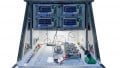
By considering measurement science and techniques for measuring the switching waveforms, VGS, VDS, and ID in a DPT setup, you positively impact the repeatability and reliability of your results. Before addressing the specific measurements, let’s first analyze the basic DPT setup (Figure 1).

Figure 1: Basic Double Pulse Test Setup
We’ve added additional detail to the diagram from April’s article to highlight several important considerations. All measurement instrumentation is referenced to earth ground. Oscilloscope inputs are single-ended when using conventional probes, with the ground leads essentially being at earth ground potential. For many power supplies, the + and – terminals “float” from earth ground to a specified limit (i.e. Maximum voltage between earth and output terminal is 500V). This isolation from earth ground can be modeled as isolation impedance (Zi) for these instruments. Likewise, many Waveform/Function Generators are isolated from earth ground, typically ± 42V. Why is this important?
Common Mode Effects
Ideally, we’d like to assume earth ground is the same potential across our DPT setup and there is no current flowing in earth ground. The reality is there are differences in potential between the earth's ground contact points, which are referred to as common mode voltages (Vcm in Figure 1). The common-mode voltages induce common mode ‘error’ currents that impact our measurement instruments (i.e. oscilloscope). Even the isolated instruments (e.g. HV power supply) provide common-mode current return paths through Zi, especially as we consider the higher frequency energy switching in the setup. Therefore, common-mode currents need to be addressed in the DPT setup.
Typical DPT setups use the HV power supply to charge the DC-Link Capacitor with the energy needed to complete a single instance of the DPT. To eliminate potential common mode currents, the power supply should be disconnected using switches (Figure 1) from the DPT setup prior to executing the DPT test. This technique addresses the concern of any common-mode coupling from the power supply. Similarly, the Waveform Generator is typically isolated in the Gate Driver, removing any potential for common-mode coupling.
The oscilloscope is a different challenge. It is the instrument that measures the DPT waveforms. Without differential or isolated probes, conventional oscilloscope probes will have long “earth referenced” return paths from the point of measurement, making them susceptible to common-mode noise. There are also challenges in making the VGS, VDS, and ID measurements without isolated/differential probes.
To start with, most DPT setups test the low side device (i.e. DUT in Figure 1) to avoid large common-mode voltages present when testing the high side device. Additionally, if making ID measurements with a shunt, one can arrange the voltage probe measuring the shunt by placing the ground lead at the same node the ground leads are connected for VGS and VDS measurements. This establishes the DUT ‘source’ terminal as the earth ground reference point in the setup, enabling the three measurements to be made without isolated or differential probes. The trick then is to reverse the polarity of the voltage measured across the shunt to determine ID.
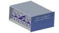
We still have the problem of common-mode currents flowing through the oscilloscope probes, in both the center conductor and shield. To minimize this error, the probes are wound through a ferromagnetic core or common mode choke (Figure 2). Because the common-mode current in the probe center conductor and the shield flow in the same direction, the associated fluxes in the core add together. This effectively creates a larger opposing magnetic field to the common-mode current. Whereas, for the differential (desired) mode current, the fluxes in the core cancel, removing the opposing magnetic field and therefore, allowing the differential signal to pass through the probe to the oscilloscope.

Figure 2: Common Mode Choke
Having established some basic understanding of the DPT setup, let’s look at some of the specific measurements.
VDS Measurement
One major challenge of measuring VDS is the large dynamic range required to measure it in both the “ON” and “OFF” states. In the “ON” state, the DUT is conducting, and the voltage drop from drain to source is small (1V - ~10V). It is critical to make an accurate measurement because RDS (on) is calculated from this VDS measurement divided by the corresponding ID measurement. In the “OFF” state, the DUT is blocking the operating voltage selected for the test (> 1000V). With 2-3 orders of magnitude difference between the measurements, it requires a much larger dynamic range than is afforded with an oscilloscope.

Figure 3: Simplified VDS Clamp Circuit and Graph
For measuring VDS when the DUT is off, we use an appropriate high voltage probe based on the operating voltage selected, which will attenuate the signal within the oscilloscope’s range. To measure VDSwhen the DUT is on, we want to use a standard 10:1 probe to get the most accurate measurement possible. We do this using a clamp circuit. The goal of the clamp circuit is to limit the voltage applied to the oscilloscope when the DUT is turned off, so it does not damage the oscilloscope. But when the DUT is turned on, allow the signal to pass, measures the low VDS voltage. The simplified schematic and graph illustrate the capability of the clamp circuit (Figure 3).
For VIN less than VCLAMP – VTH, there is a linear 1:1 relationship between VIN and VOUT. When VIN reaches VCLAMP – VTH, the FET turns off and effectively clamps VOUT just below the VCLAMP voltage, regardless of the value of VIN. All you need to do is select a clamp voltage that is above the expected VDS(on) value and below the maximum input voltage of the oscilloscope. The result is an accurate measurement of VDS(on), when the DUT is turned on and a clamped voltage when VIN is greater than VCLAMP.
ID Measurement
In general, current measurements are more difficult than voltage measurements for DPT setups. One of the main limiting factors is bandwidth. As mentioned in our April article, the frequency content of DPT signals is increasing dramatically, requiring higher and higher bandwidth measurements. Most current sensor bandwidths are typically less than what is needed for faster DPT measurements. Rogowski coils are attractive current sensors because they are cheap, relatively easy to set up and use the changing magnetic field from a conductor to measure the current. However, they do require connecting their sensor loop around the conductor to be measured. This is not feasible with some setups. Additionally, they have limited bandwidth ~30 MHz and are also not able to measure DC current. A bandwidth of several hundred MHz is important for measuring the current of faster power semiconductors.
Current shunts are another way to measure current. The current flows through a “known” precision shunt resistor, developing a measurable voltage used to subsequently calculate the current. Current shunts require breaking the current path to insert them into the circuit of interest. It is important to have a low impedance to minimize the influence of the shunt in the circuit. Some commercially available shunts specify bandwidths in the 100s of MHz. We characterized the S21 transfer function of several shunts (same model and specification) to see how consistent their bandwidth was (Figure 4).

Figure 4: S21 transfer function of coaxial shunts
The 3dB bandwidth of these shunts ranged from ~ 25 MHz to ~ 280 MHz, more than an order of magnitude variation in performance! This difference significantly impacts the waveforms captured in a DPT measurement (Figure 5). You notice more overshoot for ID with the 25 MHz shunt compared to the 280 MHz shunt, distorting the power waveform that is ultimately used to integrate e(ON). This distortion is an artifact of the shunt, not the power device. Therefore, the 25 MHz shunt ultimately results in a larger and incorrect e(ON), extracted from the distorted waveform.
Signal Skew
We can’t discuss measurement challenges for dynamic testing without mentioning the aspect of signal skew. Because of the high frequency and sharp edge transitions in DPT waveforms, it is important to realize there are different signal paths through each oscilloscope probe out to each measurement point. These different paths impact the propagation of each signal resulting in signal skew (Figure 6). Depending on which signal (VDS or ID) is delayed, e(ON) and e(OFF)calculations could underrepresent or overrepresent the resulting switching loss.

Figure 5: Impact of BW on current shunt measurements

Figure 6: Time skew in oscilloscope inputs, measured on DPT fixture
Conclusion
The Keysight PD1500A Dynamic Power Device Analyzer/Double-Pulse Tester was developed to solve these measurement challenges. In addition to supporting the common-mode recommendations and a modular clamp circuit, we’ve developed and implemented compensation techniques to address the other issues we’ve raised. Specifically, we have a software guided routine to adjust the oscilloscope and probes to eliminate signal skew at the DPT fixture.
Additionally, we characterize each shunt resistor used in our systems in the factory by measuring the S21 transfer characteristic up to 400 MHz. We then compensate for that specific’s shunt’s characteristics, essentially flattening the frequency response and eliminating distortion from low bandwidth shunts. As in many Keysight solutions, we provide an autocalibration routine. This software guided routine uses an accurate Source Measurement Unit (SMU) with 100 nV resolution as an internal system reference.
Measurement points across the range of each oscilloscope channel/probe pair are compared to the corresponding SMU reference values. From this data, gain and offset errors are determined and compensated for in the system, providing improved accuracy and more repeatable results. Figures 7a and 7b, illustrate the possible impact on your DPT measurement results when using the compensation techniques described. We measured DPT wave-forms and extracted e(off) from a SiC MOSFET (1200V, 40A) with the same operating conditions (800V, 30A, Rg=10Ω, room temperature) with and without compensation.
Figure 7a shows the DPT waveforms and extracted results without compensation. As we might expect, the ringing in ID, and consequently the power (VDS * ID), is more exaggerated in these wave-forms, undoubtedly due to a lower bandwidth shunt. Combined with the other potential signal skew and autocalibration errors, the resultant extracted e(off) result is 218.50 μJ. Compare this to Figure 7b where we used compensation techniques. The ringing is reduced and the extracted e(off) result is 296.60 μJ. In the case of e(off) for this device, the PD1500A measurement techniques remove a 26% error caused only by incorrect measurement science!

Figure 7a: E(off) waveforms and extraction without compensation

Figure 7b: E(off) waveforms and extraction with compensation
Keysight designed the PD1500A Dynamic Power Device Analyzer as a complementary dynamic characterization solution to the B1505A/B1506A Power Device Analyzers you’ve learned to count on. We focused on providing repeatable and reliable dynamic DPT measurements for discrete Si/SiC-based power semiconductors. We are continuing our R&D investment in state-of-the-art measurement techniques for DPT solutions. Stay tuned for new solutions focused on discrete GaN and Si/SiC power modules.
To learn more about Keysight’s PD1500A Dynamic Power Device Analyzer, please visit the website and view the video demonstrating its operation. Look for future articles from Key-sight, with more discussion regarding repeatable and reliable Double-Pulse Test results.
Authors: Mike Hawes, Keysight Power Solution Consultant; Ryo Takeda, Keysight Solution Architect; Bernhard Holzinger, Keysight Technical Architect; Michael Zimmerman – Keysight R&D Engineer
This article originally appeared in Bodo's Power Systems.