Facebook
 Google
 GitHub
 Linkedin
Smart Appliances Need a Smart Power Supply with Clever Standby Power Management
This article presents an approach to minimize the overall standby power for household appliances using advanced technology and power architectures.
You know that most electrical and electronic household and office equipment consume electric power when switched off or not performing their primary function. This standby power is mostly wasted.
Worldwide, standby losses are a significant part of total electricity use. Recognizing this, since the beginning of the twenty-first century many voluntary and mandatory programs have taken aim at reducing standby power (and its associated CO2 emissions).
Household periodical appliances that users turn on and off, such as washing machines, coffee machines, and the new robotic vacuum cleaners, typically have two phases for power loss when idle:
- The “left-ON mode,” is when the appliance has finished its working cycle and remains switched on; this phase may persist for an indefinite time after the completion of the cycle without further intervention of the user.
- The “OFF-mode,” is, as you might guess, when the appliance is turned off, automatically or by the user.
To achieve the highest labelling grade, it makes sense to limit the duration of the left-ON mode and force the appliance to enter the OFF-mode automatically when it completes its working cycle. In fact, IEC62301 Clause 4.5 for energy-consumption calculation labelling, allows that if the consumption of the appliance is lower than 5 mW in the “OFF-mode,” no contribution at all to energy consumption needs to be considered while the device is not performing its primary function.
Other household continuous appliances, such as a refrigerator, always stay ON and must be highly efficient in light-load condition that is where they operate for the major portion of their life.
This paper presents an approach to minimize the overall standby power for a household appliance using advanced technologies and clever power architectures, which enable SMPS designs to meet the most demanding energy-saving regulations, thanks to:
- Advanced light-load management that allows the appliance to reach the lowest overall input power consumption under light-load and no-load conditions.
- Zero-power mode (ZPM) function that enables the appliance to shut down automatically at the end of the working cycle, consuming zero power from the power line.
Examples of the implementation of such techniques are presented with reference to two VIPerPlus high-voltage converters.
Advanced light-load management
VIPer01 is a high-voltage converter smartly integrating an 800 V avalanche-rugged power MOSFET with fixed-frequency PWM current-mode control. The integrated HV startup, sense-FET, error amplifier and oscillator with frequency jitter allow you to design a complete application (flyback, buck, buck-boost) with minimum component count.
Main features of VIPer01 to meet the most stringent energy-saving standards under light-load are:
- Low threshold of both power MOSFET and internal logic circuitry that allows to supply the IC starting from a 4.5 V supply voltage.
- Reduced gate charge of the power MOSFET and low-consumption of the internal logic circuitry allow the circuit to reach an extremely low quiescent current.
- “Pulse Frequency Modulation” (PFM) decreases the switching frequency under light-load, which minimizes all the frequency-related losses. The following sections report measurements of performance in light-load conditions.
The following sections report measurements of performance in light-load conditions.
Light-load standby performance
The measurements reported here refer to the evaluation kit STEVAL-ISA177V1, a wide-range flyback converter based on VIPer01, which delivers 4.25 W to a 5 V single output.
In no-load conditions the overall application consumes less than 10 mW at 230 VAC and its efficiency @ 250 mW output load is higher than 60%.
|
|
PIN [mW] |
|
|
POUT [mW] |
@VIN = 115 VAC |
@VIN = 230 VAC |
|
0 |
4.4 |
8.6 |
|
25 |
48.6 |
57.4 |
|
50 |
89.0 |
100.1 |
|
250 |
361.2 |
398.5 |
Table 1: STEVAL-ISA177V1 no-load and light-load performances
Best standby performance in the market
A benchmark with the most popular high-voltage converters shows that a 5 V output converter in buck topology based on VIPer01 has better performance than the average standby available in the market.
To ensure realistic comparisons, all measurements were performed using the same base board, which was equipped with: diode bridge rectification, input filter, freewheeling diode, power inductor and output capacitor.
Each sample to be tested has been placed on a separate module containing all the circuitry needed to bias and run that particular SMPS driver. Then, the modules were separately plugged into the base board.
Light-load efficiency comparison
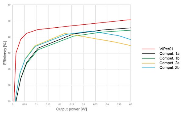
Figure 1: Efficiency at Vout = 5 V, light-load
The above charts show that VIPer01 has the best performance in terms of efficiency under light-load relative to all the considered devices.
Standby Consumption Comparison
We measured the standby power consumption by connecting a Zener diode across the output. A 15 V Zener diode has been used for 5 V output voltage, 20 V Zener diode for 12 V output and 28 V Zener diode for 24 V output voltage version. The following table summarizes standby measurements taken under different conditions.
|
Input power consumption (mW) |
|||
|
5 V |
12 V |
24 V |
|
|
VIPer01 |
10.1 |
14.4 |
39.4 |
|
Compet. 1a |
60.1 |
44.2 |
61.1 |
|
Compet. 1b |
61.4 |
20.2 |
45.6 |
|
Compet. 2a |
39.2 |
31.8 |
53.6 |
|
Compet. 2b |
37.2 |
30.8 |
53.1 |
Table 2: Standby power measured with Zener diode on the output
Advanced architecture for zero-power consumption
This section shows that VIPer0P allows designing an SMPS for periodical household equipment that automatically enters the OFF-mode at the end of the working cycle, while consuming less than 5 mW in this OFF-mode state, getting rid of the commonly used bi-stable electromechanical switches, increasing the overall reliability, and reducing the cost of the system. In fact:
- The SMPS can be shut down by a microcontroller (MCU) supervising the operation of the appliance and enter a special state where it delivers no power at its output terminals.
- Once in this state, the SMPS is ready to be manually restarted by the user while consuming less than 5 mW from the power line at 230 Vac.
This capability is a “zero-power function”, an innovative feature of VIPer0P which is described hereafter and defined by IEC62301 Clause 4.5.
Zero-power function
In addition to the features for advanced light-load management listed in section 2.1, the key feature of the VIPer0P is the “zero-power function,” whose principle schematic is shown in Figure 2. It consists of a special idle state (Zero-Power Mode, ZPM) where the control IC is totally shut down - except for the circuitry necessary for exiting ZPM - and the high-voltage start-up cell does not perform its usual function. The high-voltage start-up cell is the current generator used to start-up the device from the rectified power line directly by charging its Vcc capacitor Cs above the start-up threshold.
Assuming that the device is operating normally, when the OFF pin voltage is pulled to GND for more than 10 ms (debounce time for immunity to disturbances), the “zero-power logic” block asserts the signals SD and ZP high. SD asserted high disconnects nearly all the blocks of the control chip from the Vcc supply line, so that it is shut down with the gate of the main MOSFET pulled low. This stops the SMPS. The only parts of the control IC that remain alive are the “zero-power logic” block and the 4 V regulator that provides the bias voltage to it.
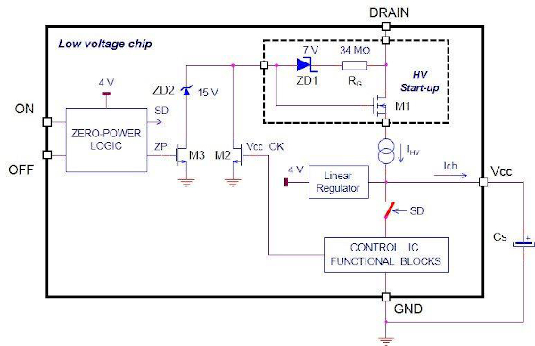
Figure 2: Principle schematic of the zero-power function of VIPer0P
ZP signal asserted high turns M3 on and fixes the voltage of the gate terminal of M1 at about 15 V through the Zener diode ZD2. In this way, the Vcc voltage is set at about 13 V. The 4 V linear regulator supplied from Vcc provides those few μA needed to operate and keep the “zero-power logic” block alive. Both pins ON and OFF are internally connected to this 4 V supply line via 50 kΩ pull-up resistors, so either of them can be used to provide a small current to some external circuit.
The overall consumption in ZPM consists of two components: that on the branch ZD1, RG, ZD2, M3 and that due to the quiescent current Iq (≈ 1.5 μA) absorbed by the 4 V regulator and the “zero-power logic” block plus the current Iext delivered to an external circuit.
This consumption may be estimated as follows:
with obvious symbolism. At Vin = 230 Vac and with worst-case values (RG = 28 MΩ, VZD1 + VZD2 = 20 V, Iq = 2 μA) it is PZPM = 4.2 mW + 0.325 mW/ μA of Iext.
To exit ZPM, the ON pin voltage must be pulled to GND for more than a 20 μs debounce time. By doing so, the “zero-power logic” block asserts the signals SD and ZP low. ZP asserted low turns M3 off and releases the gate terminal of M1, while SD asserted low reconnects the blocks of the control chip to the Vcc supply line, held at 13 V by the Vcc capacitor Cs. This voltage is well above the start-up threshold of the IC (8 V), so the high-voltage start-up cell is disabled by M2 turned on and switching activity restarts immediately.
A practical example on zero-power architecture
The demonstration board STEVAL-ISA174V1 is a wide-range input, 6.8 W two-output non-isolated flyback converter designed with the VIPer0P.
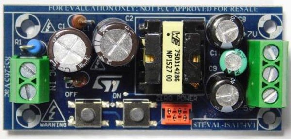
Figure 3: STEVAL-ISA174V1 (64 x 29 mm)
It delivers 4 W on a - 5 V output tightly regulated through a voltage divider connected to the non-inverting input of the error amplifier available at the FB pin; and 2.8 W to a + 7 V output, semi-regulated by magnetic coupling through the turn ratio of the two output windings.
The demonstration board has been completely characterized and is described in AN4836, here only the results related to energy saving requirements are reported. In particular, this application complies with the tightest references for energy-conscious designs, such as European CoC ver. 5 requirements for external power supplies.
The data in Table 3 show that the application, when in zero-power mode (ZPM), is ratified to have zero-power input consumption as per IEC62301 Clause 4.5 and is Five-star energy efficient when operating with no load.
|
Vin |
ZPM input power consumption [mW] |
No-load input power consumption [mW] |
|---|---|---|
|
115 Vac |
0.8 |
6.5 |
|
230 Vac |
3.5 |
9.1 |
|
Conditions |
- Power line connected - IC not switching, most internal blocks disabled - Iout1 = Iout2 = 0 - Vout1 = Vout2 = 0 |
- Power line connected - IC switching (burst-mode) -Iout1 = Iout2 = 0 - Vout1 and Vout2 regulated at their nominal values |
Table 3: ZPM input power and no-load input power of STEVAL-ISA174V1
The data in Table 4 show that the equivalent 12 V / 6.8 W SMPS (simply obtained connecting the load across the Vout1 and Vout2 lines) is compliant with the ErP Lot 6 Tier 2 requirements in off-mode (same as ER 1275/2008) and the 10% load efficiency target envisaged by the European CoC ver. 5.
|
Vin [VAC] |
Efficiency [%] |
|||
|---|---|---|---|---|
|
|
@ POUT = 25 mW |
@ POUT = 50 mW |
@ POUT = 250 mW |
@ POUT = 680 mW |
|
115 |
55.6 |
60.8 |
72.2 |
78.0 |
|
230 |
51.3 |
57.0 |
66.3 |
71.4 |
Table 4: Light-load performances of STEVAL-ISA174V1
STEVAL-ISA174V1 is a demonstration board and does not include MCU, thus ON and OFF pin are activated by the user through push buttons. Other evaluation kits that include the MCU are STEVAL-ISA181V1 and STEVAL-ISA192V1.
Figure 4 shows two examples of ways the pins ON and OFF can be operated.
With the arrangement (a), the MCU supervising the operation of the appliance shuts down the SMPS by pulling low OFF pin voltage through one of its GPIO pins, cutting also its own supply voltage. The restart is commanded by a pushbutton or a tactile switch pressed by the user that directly operates pin ON. The MCU wakes up after the SMPS is again up and running. This arrangement provides the minimum consumption from the power line.
With the arrangement (b), the MCU shuts down the SMPS by pulling low OFF pin voltage and wakes it up as well by pulling low ON pin voltage. Two of its GPIO pins are used. The MCU (rated for 3.3 V supply voltage) is powered also during ZPM, so it must be equipped with advanced features of power management such as an ultra-low consumption standby mode with fast wake-up. This arrangement is implemented in the evaluation kit STEVAL-ISA192V1.
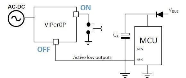
(a) Automatic ZPM with manual turn ON
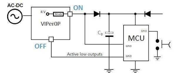
(b) ZPM fully managed by MCU
Figure 4: Examples of ZPM management with an MCU and a touch button
Conclusions
Today power supply units require more sophisticated methods for improving performance to meet the energy-saving regulations’ push for greater efficiency.
ST’s VIPerPlus high-voltage converters combine an 800 V avalanche-rugged power section, a state-of-the-art PWM control circuitry, with advanced technologies and clever power architectures to meet the need for increasingly efficient electrical power in smart household appliances that have to be connected with an advanced user interface.
VIPer01 applications demonstrate how easy it can be to meet the most stringent energy regulations for continuous household appliances. On the other hand, VIPer0P applications demonstrate how to build a clever standby architecture with easy interaction with the MCU to reduce the bill of materials cost of a power supply for a periodical household appliance.
The result is an SMPS design that meets the most demanding energy-saving regulations and more: high reliability, flexibility, and minimal component count.
This article originally appeared in the Bodo’s Power Systems magazine.
About the Author
Mirko Sciortino works as an Application Engineer at STMicroelectronics, Geneva, Switzerland. He is responsible for proposing and designing switching power supplies applications; fully supporting customers in developing, running and optimizing their applications; and proposing and fixing new devices' specs, working together with the Design and Marketing Departments. He earned his Laurea (equivalent to Bachelor of Science in the European university system) in Electronics at the University of Palermo, Palermo PA, Italy.