Facebook
 Google
 GitHub
 Linkedin
Digital Power Electronics Basics: Digital (Binary) Operation
Learn about the binary system employed in digital electronics.
Digital electronics, unlike analog electronics, do not handle the continuous voltage and current signals; Instead, it uses electrical signals that only have two possible conditions or states. Electronic engineers and students must understand the fundamentals of digital electronics fully.
Analog and Digital Signals
There are two basic methods of representing the numerical values of the physical quantities we constantly handle.
One method, referred to as analog, assumes that the quantity can take any value in a specified continuous range between two expected extreme values.
Figure 1 shows an analog signal representing the amplitude of a human voice.
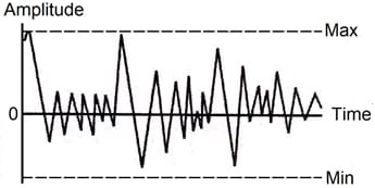
Figure 1. Analog signal.
With the other method, denoted as digital, the signal can only take some pre-specified discrete values.
Unlike analog signals, the amplitude of a digital signal ideally varies abruptly between its possible discrete values, with no intermediate states or phases. Usually, binary numbers represent the values.
Figure 2 shows three digital signals where the signal can take only two different values (the Min and the Max values). Notice how the amplitude suddenly changes between the two states.

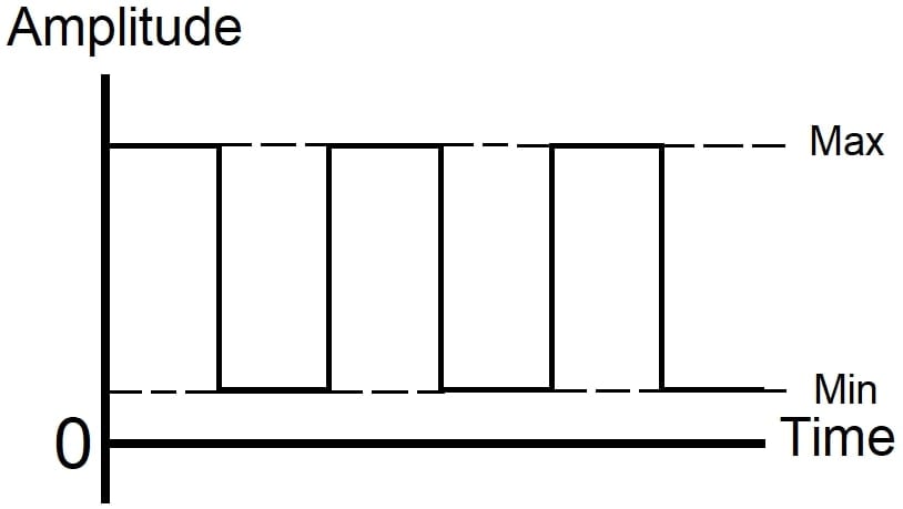
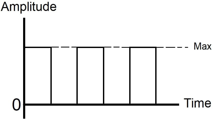
Figure 2. Digital signals.
To summarize, analog devices process physical quantities in the analog form giving a continuous output, while digital systems process physical quantities in digital format, generating signals that can take only some pre-specified discrete values.
Digital (Binary) Operation
The study of number systems is essential to understand the representation of the data before processing them in any digital technique, including digital computers.
The advent of computers popularized the base 2 or binary system. A digital system functions in a binary way, employing devices that exist only in two states. A transistor can normally have only two states in a digital system: it is either ON or OFF.
Several terms designate these two quantized states. Table 1 shows some standard state labels.
| True | High | 1 | On | Closed |
| False | Low | 0 | Off | Open |
Table 1. Some binary-state terms.
Logic statements can be true or false. A voltage may be high or low. A switch may be closed or open. A transistor may be on or off.
The best symbols for mathematically manipulating switching operations and logic functions are 0 (zero) and 1 (one).
The number of different digits or symbols used in a number system is the radix or base of the system.
A decimal system has 10 independent digits: 0, 1, 2, 3,…, and 9. Then, the radix or base is 10.
The binary has two different digits, 0 and 1, and is a radix-2 or base 2 number system. A binary digit is a bit, a word that systems engineers translate into all languages. A group of bits creates a byte, word, or code.
In the base 10 system, numbers larger than 9 are represented by an array of digits. The number farthest to the right means “a value less than ten.” A number to the left of that means “some tens less than 100.” A number to the left of that means “several hundred less than 1,000,” and so on.
So we understand 753 to mean three and five tens and seven hundred – or seven hundred and fifty-three.
Also,
753 = 7∙10² + 5∙10¹ + 3∙10º
Where the individual digits are multiplied by the coefficients corresponding to the digit position (the coefficients are powers of ten).
In the binary system, the digits 0 and 1 should be multiplied by coefficients that are powers of 2 rather than 10 as in the decimal system.
The binary representation of the decimal number 753 is 1011110001, since
1011110001 = 1∙2⁹ + 0∙2⁸ + 1∙2⁷ + 1∙2⁶ + 1∙2⁵+ 1∙2⁴ + 0∙2³ + 0∙2² + 0∙2¹ + 1∙2º = 753
Table 2 shows a few equivalent numbers in decimal and binary notation.
| Decimal | 0 | 1 | 2 | 3 | 4 | 5 | 6 | 7 | 8 | 9 |
| Binary | 0 | 1 | 10 | 11 | 100 | 101 | 110 | 111 | 1000 | 1001 |
| Decimal | 10 | 11 | 12 | 13 | 14 | 15 | 32 | 64 | 255 | 256 |
| Binary | 1010 | 1011 | 1100 | 1101 | 1110 | 1111 | 100000 | 1000000 | 11111111 | 100000000 |
Table 2. Equivalent numbers in decimal and binary notation.
The binary number system has substantial advantages over other number systems for use in computer systems.
Logic 1 and Logic 0
In switching systems, it is crucial to understand the relationship between logic 1 and logic 0 and the polarities of the signal voltage. Any signal, positive or negative, can be assigned logic value 1 – but not both in the same system. If a positive voltage represents logic 1, the zero or negative voltages represent logic 0.
These positive and negative voltages are relative to each other and do not need to be positive or negative with respect to the reference or circuit ground – the absolute values are of no significance in these definitions. In this way, if a positive voltage represents logic 1, a less positive voltage can be used to represent logic 0 since it is negative with respect to the logic 1 signal.
Likewise, if a negative voltage represents logic 1, a positive voltage with respect to it can be used to represent logic 0, even if it equals zero since it is positive with respect to the logic 1 voltage.
Sometimes the positive voltage represented by logic 1 is called high state, and the negative voltage represented by logic 0 is called low state. But it can also be the reverse; that is, the high state corresponds to the most negative voltage and the low state to the most positive voltage.
Many electrical and electronic circuits may generate digital signals. A light-emitting diode (LED), for example, has only two well-defined states of operation: on or off. Each of these two conditions may be associated with a logical state that may be 1 or 0, that is:
LED on: logic 1 ( or 0)
LED off: logic 0 ( or 1)
Positive Logic and Negative Logic
When logic 1 corresponds to the highest voltage of the digital signal and logic 0 corresponds to the lowest voltage, the circuit employs positive logic. In contrast, when logic 1 corresponds to the lowest voltage value of the digital signal and logic 0 corresponds to the highest voltage, the circuit uses negative logic.
Figure 3 shows positive logic digital signals and figure 4 negative logic digital signals.
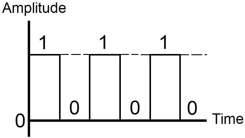
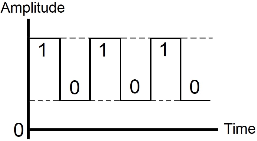
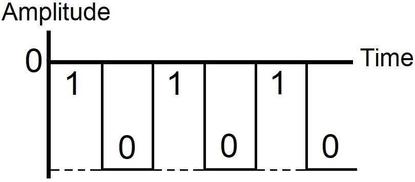
Figure 3. Positive logic.
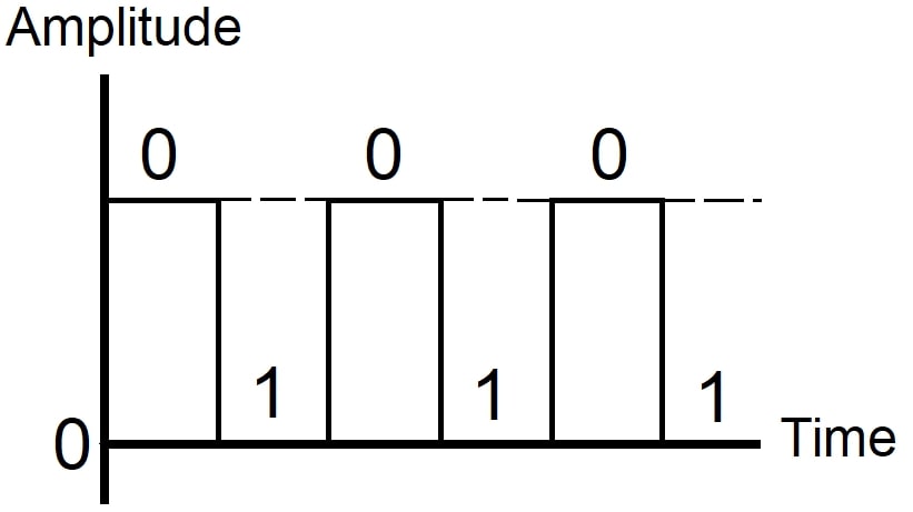
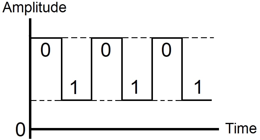
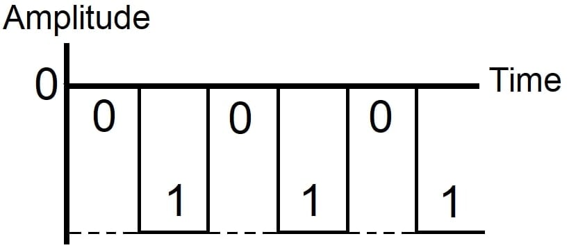
Figure 4. Negative logic.
Logic Circuits
Digital computers, telephone, and industrial electronic control systems use complicated switching circuits to do their jobs economically and efficiently.
Considering a single switch, it has an off state and an on the state.
A combination of switches can be used to design sophisticated digital systems that are governed by “logical” orders. These systems allow us to turn on a given switch only after meeting specific conditions. These systems are usually so complicated that you cannot organize, design, and assemble it by mere observation or intuition.
Since numerous logical conditions must govern switching, the design and assembly of these systems require an orderly study that includes specific rules of logic. The best tool to design efficient switching systems and analyze their operation characteristics is the Boolean algebra, named after its creator, the English logician and mathematician George Boole (1815-1864).
Computers operate on the principles of Boolean algebra. Boolean algebra deals with the study of variables limited to only two values: one and zero. These values correspond to the on and off states of an electrical or electronic circuit.
Various logic graphs and diagrams supplement Boolean algebra. Among them, we have the Karnaugh diagrams and the Venn diagrams. They provide a graphical representation of certain switching states and are of great value to produce effective switching systems.
Understanding Digital (Binary) Operation
- Analog signals vary in amplitude as a function of time, assuming any value between two expected maximum and minimum values.
- Digital signals can only take some pre-specified discrete values.
- The decimal number system is radix-10, having 10 different digits or symbols.
- Digital electronics employ a binary system.
- The binary is a radix-2 number system having 2 different digits: 0 and 1. Binary numbers are represented in terms of 0 and 1.
- The binary variables can have a logic 1 or a logic 0 state, represented by two voltage levels or two current levels.
- In a positive logic system, the more positive of the voltage or current levels represents a logic 1 and the less positive represents a logic 0.
- In a negative logic system, the more positive of the voltage or current levels represents a logic 0 and the less positive represents a logic 1.
- George Boole introduced the mathematics of logic, reducing it to a binary notation of 0 and 1 – which is the foundation for modern digital computer operation.
Featured image used courtesy of BrainKart
Related Content