Facebook
 Google
 GitHub
 Linkedin
Automatic Magnetic Simulation Generation for Inductive Components Design
This article highlights PERMO GaN and SiC technologies which permit to obtain the most efficient converters in the smallest size.
The current trends in power electronics tend towards higher frequencies to reduce the weight and volume of passive components. This is impulsed by the development of semiconductors in GaN and SiC technologies which permit to obtain the most efficient converters in the smallest size. Nevertheless, a higher switching frequency brings new problematics for the magnetic components design.
Additional losses due to skin-depth reduction, proximity effect between conductors or fringing flux effect can become very important to be fully considered. Of course, it exists some analytical models to estimate their level, but they remain quite complex or require many hypotheses for an easy and accurate application in the Industry. Another way to estimate their amount can be the use of Finite Elements Analysis simulation (FEA). However, from an industrial point of view, the cost of such software and the time spent to build each mechanical model remain a limitation. To answer to this concern, a new fast and cheap v will be presented.
The main interest of the presented method is to estimate easily and cheaply in an automatic way the additional losses in a magnetic component. Building the model with an automatic generation also permits to reduce the risk of human errors in the geometric construction or in the input data.
Globally, the problem is introduced on a Mathcad® [1] page with all the requirements about the operation (buck/boost/filter choke, flyback/ bridge transformer…) and its related electrical values as well as with the first estimated set of dimensions, turns and conductors to calculate the DC resistance, RMS current and flux density values... Analytically, the DC copper and core losses can be already estimated from well-known models [2,3] by robust analytical calculations.

Figure 1: Flow chart of the method.
With the switching frequency increase in converters, the phenomena causing additional copper loss in windings are well identified [4,5,6,7], but their impact is difficult to solve analytically for real components without using important hypotheses or time-consuming 3D model introduction in FEA software at first.
To be quick and with no license fees, the FEMM® [8] software has been selected to quickly solve the Maxwell’s equations in 2D and show the impact of frequency effects in conductors. Its postprocessor is used to calculate the AC losses according the ripple of current at the specified frequency.
The GNU-Octave® [9] scientific programming language (to define the script and parametrize the simulation) is used to operate the coupling between analytical calculations and FEA approaches (Figure1). The parameters are passed through a matrix (.mat). The script can also launch postprocessing calculation and pre-defined strategies like harmonics study to be more accurate in the results.
Filtering Coil Example Firstly, the method has been implemented for a filtering choke with a 3-turn flat wire coil and core with gap.

Figure 2: Part of the Mathcad routine (current waveform to calculate Irms and Bpk).
1. Mathcad calculations
The method begins in a home-made Mathcad routine with equations related to the component operation. Several modules have been developed yet for chokes with gap, flyback or bridge transformers... The electrical behavior is translated into voltage and current waveforms by pieces of straight lines to be able to calculate the RMS current values (Irms) in windings and the maximum flux density (Bpk) in the selected core format and copper turns (Figure 2).
Frequency, temperature, input voltage range, current level… are all set as variables for automatic calculation on the Mathcad sheet. From it, the DC copper and core losses can be already computed as well as the possible gap length estimation. At the end of the file, the needed information for FEA simulation are transmitted to Octave thanks to a matrix (Figure 3).

Figure 3: Matrix of parameters used for Mathcad-Octave coupling.
2. Octave script
An existing Octave [7] package provides functions which can be used to control FEMM and parametrize a simulation from a script file. The developed script opens FEMM and generates the simulation (2D axisymmetric or planar type) according to the data available in the matrix generated by Mathcad (geometry construction, assign physical properties, set boundary conditions).

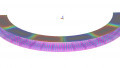
Figure 4: Current density in conductors generating extra AC losses.
3. FEMM processing
After automatic generation (in a few seconds only) of the result on figure 4 where the influence of the fringing flux out of the gap and proximity effect between turns can be clearly seen, the AC copper losses from the first harmonic are computed here at 1.7W (100°C) that is of the same amount as the DC copper losses! The postprocessor can also be used to check the inductance value or the magnetic field inside the core…
Transformer Case
Another Mathcad file and Octave script have been created to extend the method to multi-winding transformers. The geometrical data (Figure 5a) of the core and bobbin are defined in a Mathcad file and sent to Octave with also the electrical parameters for the simulation. The windings are defined in a matrix (Figure 5b) which represents the circuit numbers (in line) per layers (in column); the value in the cell gives a number to the circuit to which the current level will be assigned. The real part of the currents Ii is defined to respect the equation (1) and the imaginary part at the primary is creating the flux in the core (Ni is the number of turns in each circuit). FEMM Litz wire integrated model [10] can be directly used if conductors are of this type.
Σ Ni Re (Ii) = 0 (1)


Figure 5: Transformer geometry (a) and winding matrix (b).
Conclusions and Future Work
A method for automatic generation in a 2D FEA software is presented for a quick estimation of the complementary AC copper losses in windings due to frequency effects. It combines Mathcad-Octave- FEMM software at almost no cost with a very fast computation and no manual geometry introduction. Linked to analytical models, it enables a more realistic estimation of the total loss in magnetic components.
Further to the axisymmetric examples presented here for a filtering coil and a 2-winding transformer, 2D planar types will be introduced to consider other geometries like ring cores or low-profile magnetic circuits. Moreover, the automatic generation and programmed control of post-processor will be used to introduce pre-defined Fourier analysis. The purpose of this analysis is to get the AC losses contribution for all the possible harmonics of the current. Eventually the link with thermal simulation in a similar way will be studied to get the temperature map.
References
[1] PTC User’s Guide – Mathcad 14.0 Parametric Technology Corporation, ©2007
[2] Colonel Wm. T. McLyman “Transformer and Inductor Design Handbook” KG MAGNETICS Inc., Third Edition, 2004, 533p.
[3] FERROXCUBE Soft Ferrite Design Tool – Help file, “Power Loss Calculation” Ferroxcube SFDT 2010 3.1, April 2010, pp.36-41
[4] Peter Markowski “Magnetic components design : 3D Electromagnetic Simulation Allows Reduction of AC Copper Losses” Transformers Magazine, Volume 2 - Issue 1, pp.66-72
[5] P.L. Dowell “Effects of Eddy Currents in Transformer Windings” IEE Proceedings, Vol. 113, No. 8, August 1966
[6] Lloyd H. Dixon, Jr “Eddy Current Losses in Transformer Windings and Circuit Wiring” Texas Instrument, slup197, 2003
[7] Bernard Multon. “Composants passifs de l’électronique de puissance (magnétiques et capacitifs)” ENS de Cachan, France, February 2006, 90p. ISBN 2-9099968- 70-7
[8] David C. Meeker FEMM User’s Manual, “Finite Element Method Magnetics” Version 4.2, October 2015, 161p.
[9] GNU-Octave User’s Guide – Version 5.2.0 John W. Eaton, ©1996-2020
[10] David C. Meeker “An Improved Continuum Skin and Proximity Effect Model for Hexagonally Packed Wires” ELSEVIER, Journal of Computational and Applied Mathematics, April 2012, pp.4635-4644
This article originally appeared in Bodo’s Power Systems magazine.
About the Author
Patrick Fouassier works as the Research and Design Manager at Premo Group, France. He is responsible for the development and project management of innovative solutions for the automotive sector with components for battery chargers and DC/DC converters from some kW to tens of kW used in new electrical and hybrid cars. He earned his Bachelor's Degree in Electrical Engineering and his Ph.D. in Electrical Engineering both at the National School of Energy, Water and Environment (Grenoble INP - Ense3), one of the engineering schools of the National Polytechnic Institute of Grenoble.
Benoît Battail worked as R&D Engineer at PREMO FRANCE.