 Facebook
 Google
 GitHub
 Linkedin
Resistor Color Code
How Does the Resistor Color Code Work?
Check out the All About Circuits Resistor Color Code Calculator, a handy tool for reading resistor color code values.
Resistor values are often indicated with color codes. Practically all leaded resistors with a power rating up to one watt are marked with color bands. The coding is defined in the international standard IEC 60062. This standard describes the marking codes for resistors and capacitors. In addition to defining the color bands, the standard also includes numerical codes, as often used for surface mount SMD resistors.
The color code is given by several bands. Together they specify the resistance value, the tolerance, and sometimes the reliability or failure rate. The number of bands varies from three to six. At a minimum, two bands indicate the resistance value and one band serves as multiplier. The resistance values are standardized; these values are called preferred values.
Resistor Color Code Chart
The chart below shows how to determine the resistance and tolerance for resistors. The table can also be used to specify the color of the bands when the values are known. An automatic resistor calculator can be used to quickly find the resistor values.

Tips for Reading Resistor Codes
In the sections below, examples are given for different numbers of color bands. But, first, here are some general tips for reading the color code:
- The reading direction might not always be clear. Sometimes the increased space between bands 3 and 4 provide an indication of the reading direction. Also, the first band is usually the closest to a lead. A gold or silver band (the tolerance) is always the last band.
- It is a good practice to check the manufacturer’s documentation to be sure about the color coding system used.
- When in doubt, measure the resistance with a ohmmeter. In some cases this might even be the only way to figure out the resistance; for example when the color bands are burnt off.
4 band resistor
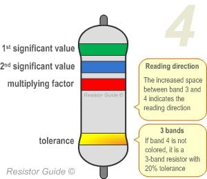
The four band color code is the most common variation. These resistors have two bands for the resistance value, one multiplier and one tolerance band. In the example shown here, the 4 bands are green, blue, red and gold. By using the color code chart, one finds that green stands for 5 and blue for 6. The third band is the multiplier, with red representing a multiplier value of 2 (102). Therefore, the value of this resistor is 56 · 102 = 56 · 100 = 5600 Ω. The gold band means that the resistor has a tolerance of 5%. The resistance value lies therefore between 5320 and 5880 Ω (5560 ± 5%). If the tolerance band is left blank, the result is a 3 band resistor. This means that the resistance value remains the same, but the tolerance is 20%.
5 band resistor
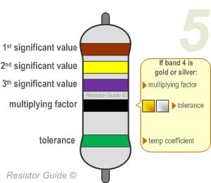
Resistors with high precision have an extra band to indicate a third significant digit. Therefore, the first three bands indicate the significant digits, the fourth band is the multiplication factor, and the fifth band represents the tolerance. For the example shown here: brown (1), yellow (4), violet (7), black (x 100 = x1), green (0.5%) represents a 147 Ω resistor with a 0.5% tolerance.
There are exceptions to this 5-band color system. For example, sometimes the extra band may indicate failure rate (military specification) or temperature coefficient (older or specialized resistors). Please read the subsection “Color Code Exceptions" below for more information.
6 band resistor
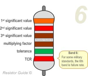
Resistors with 6 bands are usually for high precision resistors that have an additional band to specify the temperature coefficient (ppm/˚C = ppm/K). The most common color for the sixth band is brown (100 ppm/˚C). This means that for a temperature change of 10 ˚C, the resistance value can change 1000 ppm = 0.1%. For the 6 band resistor example shown above: orange (3), red (2), brown (1), brown (x10), green (1%), red (50 ppm/°C) represents a 3.21 kΩ resistor with a 1% tolerance and a 50 ppm/°C temperature coefficient.
Color Code Exceptions
Reliability band
Resistors that are produced according to military specifications, sometimes include an extra band to indicate reliability. This is specified in failure rate (%) per 1000 hours of service. This is rarely used in commercial electronics. Most often the reliability band can be found on four band resistors. More information about the reliability can be found in the US military handbook MIL-HDBK-199.
Single black band or zero-ohm resistor
A resistor with a single black band is called a zero-ohm resistor. Principally it is used as a wire link that functions to connect traces on a printed circuit board (PCB). Using the resistor package allows the same automated pick-and-place machines to place the components on a circuit board.
5 band resistor with a 4th band of gold or silver
Five band resistors with a fourth band of gold or silver form an exception and are used on specialized and older resistors. The first two bands represent the significant digits, the 3rd is the multiplication factor, the 4th is the tolerance, and the 5th is the temperature coefficient (ppm/˚C).
Deviating colors
For high voltage resistors, the colors gold and silver are often replaced with yellow and gray. This is to prevent having metal particles in the coating.