 Facebook
 Google
 GitHub
 Linkedin
Industry White Papers
Enhancing Inverter Efficiencies in Renewable Energy Systems with YMIN Capacitors
Mar 01, 2025 by Shanghai Yongming (YMIN)
With the world moving towards greener electricity solutions, the power electronics that support these systems must be designed for high efficiency. When scaled, even marginal power gains due to conversion efficiency will result in large amounts of energy saved. The inverter is a key component of the many subsystems needed to build out photovoltaic or wind-powered installations. It is the interface between the wind turbine and/or PV panels and the load, e.g., energy storage system (ESS), grid, or residence. As a result, the operation of these systems determines much of the system's efficiency and reliability cost.
Figure 1 displays how the future of renewable energy might look at the residential scale, where a solar/wind installation connects to an ESS, such as a battery bank to the home. Here, there is bidirectional energy transfer between the grid to either receive or transmit power back to the local utilities. Furthermore, a bidirectional AC/DC conversion in the EV charging allows power to be sent from the high-voltage EV battery to the residence. This distributed architecture diverges from the traditional centralized grid we often see; it operates with a much higher efficiency without the costly and lossy powerline infrastructure.
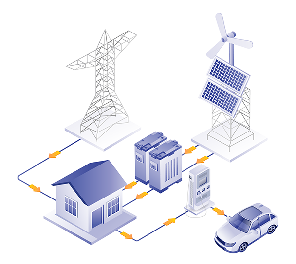
Figure 1. A modern residential energy network included complex, bi-directional power transfer.
At the heart of renewable installations is the inverter. Its internal controller will execute the algorithms to maximize the power output from wind/solar deployments and switch to ESS power during times when there may be low output power (e.g., sunset, cloudy day, etc.). When the ESS produces more power than it can use, it sells the surplus power back to the local utility grid.
An inverter plays a key role in efficient energy conversion, control and communication, galvanic isolation, and bidirectional charging and discharging in both wind and solar installations. Capacitors perform essential functions within these inverters, including ripple reduction and filtering at the input of the inverter, removing harmonic content from the output, and providing protection to sensitive internal power semiconductors. This article discusses the role of inverters in green energy and the key parameters in capacitors that must be optimized to best support these systems.
The Role of Inverters in Renewable Energy Systems
Although the inverter's performance parameters differ depending on whether it is used in a wind or solar installation, the power curves for a wind turbine and a solar inverter vary significantly (Figure 2). However, the underlying functionality remains the same: the inverter converts the incoming DC signal into a regulated AC output.

Figure 2. The IV curve of a solar cell (left) and the wind turbine power curve (right).
As shown in the IV curve of a solar cell at left of Figure 2, in order to get the maximum power output in a solar cell, it must operate at the maximum power point (PMP). At right, the wind turbine power curve shows where the turbine begins at the “cut-in” speed until it reaches the “rated” speed, at which point the turbine operates at its rated power. At the “cut-out” speed, the rotor is halted to prevent damage to the system.
PV Inverters
Solar inverters can be central or string inverters, and micro-inverters (MIs). Figure 3 shows how string inverters combine the DC voltage from a cluster of panels and convert it to AC, while MIs do this to each individual solar panel. Battery ESSs can be employed with both of these systems. For a central inverter configuration, the internal controller within the inverter switches to battery power.
The MI-based configuration has several benefits. For example, it removes the negative impacts of PV shading loss. When physical obstructions block an individual solar panel’s access to sunlight, the panel's power output will naturally decrease. However, this will negatively impact the production of the cluster of panels tied together. The deployment of MIs also allows for maximum power point tracking (MPPT) to be implemented on individual panels and eases installation and maintenance through plug-and-play capabilities.

Figure 3. The two main configurations for PV panel installations.
Wind Inverters
The variability in wind speed causes the output power from the turbine’s generator to have varying frequencies. As a result, the power must be converted into DC and converted back into regulated AC of constant frequency for main power. This configuration changes with larger wind turbine installations; instead of converting the power generated into DC, a standard high-line AC voltage is created using drives and transformers. An inverter is a key component in the distributed grid architecture because smaller wind installations are relied upon.
The Need for Capacitors
Inverter Inputs
Capacitors are used at the input, output, and in the control circuit of inverters. In a typical PV inverter (whether MI or otherwise), the DC/DC converter adjusts the PV voltage to match the DC-link voltage. The converter is designed to track the maximum power point (MPP) of the PV source (Figure 4). The DC signal is then converted into AC for the grid connection via the inverter. Filtering capacitors are used on the DC input side to ensure a cleaner signal is fed into the converter. This is achieved by removing noise and interference from the DC power source, minimizing the effects of interfering signals on the inverter circuits.
Perturbations in DC-link voltage directly translate into PV voltage, thereby making the MPPT algorithm unstable. The DC-link capacitors must be large enough to avoid transmitting DC-link voltage variabilities into the PV voltage and to remove the high-frequency voltage ripple from the first stage.

Figure 4. Solar installation with input capacitor to filter DC power from solar battery to boost converter, DC-link capacitor to suppress voltage ripples between converter and inverter, and an output filter to reduce harmonic content in final AC signal.
You can see in Figure 5 how similar principles are applied to wind deployments. As the wind turbine's speed increases, the voltage of the permanent magnet synchronous generator (PMSG) rises proportionally. This presents a risk that the DC voltage could surpass its rated voltage. In these applications, the DC-link capacitor must withstand ripple currents from both the rectifier and the inverter.

Figure 5. Wind installation with DC-link capacitor to suppress voltage ripples between rectifier and inverter, and an output filter to reduce harmonic content in final AC signal.
Inverter Output
Since solar and wind installations feed electricity to the residence and back to the grid, they must be designed to meet regional standards on power quality for mains electricity. In the US, for example, the IEEE 519 standard is used to enact limits on the amount of harmonic voltage allowed on the power grid, while the European standard for harmonic content in mains power is IEC 61000-3-2.
Inverters sometimes operate without power factor correction (PFC) for ripple compensation. Instead, output filtering capacitors are used to reduce any harmonic content, meeting the load’s requirements for high-quality AC power and ensuring compliance with grid interconnection standards. For MIs in PV applications, an electrolytic capacitor is the standard for handling this. Engineers generally prefer electrolytic capacitors to effectively control the voltage ripple because their large size allows for a high capacitance per volume.
Reliable Electrolytic Capacitors
Electrolytic capacitors are often employed in these applications due to their high capacitance density, which allows them to better smooth out ripples across the bus. However, these capacitors typically come with reliability considerations, especially at high operating temperatures where electrolyte leakage or vaporization will cause an increase in ESR and decrease capacitance. Electrolytic capacitors commonly determine the lifetime of a power converter and inverter.
Electrolytic capacitors are usually rated from 1,000 hours to 10,000 hours at maximum temperatures between 85°C and 105°C. YMIN electrolytic capacitors are designed with a high capacitance density and specified for high reliability from 6,000 to 10,000 hours at a temperature of 105°C (221oF). This lands on the upper end of the reliability spectrum, ensuring more robust inverter performance. Ideally, the capacitors will be operating well below these specified temperatures. The Arrhenius equation (shown below) is typically used to assess capacitor lifetime.

Where:
- L0 is the manufacturer's maximum rated lifetime in hours at the upper-temperature limit
- Tm is the manufacturer’s maximum rated endurance temperature
- T is the capacitor’s operating temperature.
This equation leads to the common understanding that the expected lifetime is doubled for every 10°C (50°F) decrease in temperature, massively expanding the working life of YMIN capacitors.
The Need for Reliable Capacitance in Renewables
The next-generation utility grid will rely on renewable sources such as solar and wind. At the center of these sources is their power circuitry that converts the siphoned energy into reliable AC power to be sent to a residence or back to the grid. The primary functionality of these converters and inverters revolves around effectively suppressing voltage ripples in both the rectifier and inverter while also filtering out unwanted EMI and noise These tasks call for the use of discrete capacitors, but to do this effectively, these components must have a high capacitance density.
This necessitates the use of electrolytic capacitors; however, these capacitors may be seen as the weakest link in the power signal chain, with lifetimes much shorter than the neighboring circuitry. The most common failure modes of these capacitors occur at high temperatures where the vaporization of electrolytes causes a sharp increase in ESR and a decrease in capacitance. To bypass this issue, it is important to deploy high-reliability electrolytic capacitors that are specified to withstand the highest-rated temperatures for the longest time. YMIN electrolytic capacitors fall into this category, with operating lifetimes of up to 10,000 hours at 105°C. Since YMIN capacitors store more charge within the same volume, they can effectively smooth voltage ripples and stabilize currents in these applications for enhanced conversion efficiency in renewable applications.


perdon en articulo sobre control de potencia en Relacion con los cambios de tension en redes segu IEEE tiene un error cuando la relación de voltaje sube el 10%, la potencia aumenta 21% y no 10%, por aquello de ser la razon de relaciones de voltaje elevada al cuadrado. Gracias