Facebook
 Google
 GitHub
 Linkedin
Hi everyone,
I am currently working on the design of a Wireless Power Transfer (WPT) system for an EV Charger. I am at the phase of simulating and validating the primary-side inverter driver stage before integrating the full resonant tank and secondary side.
I am using the UCC21520 isolated gate driver in LTspice, but I am facing persistent simulation stability issues that are blocking me from moving to the next phase of the project.
The Setup:
My Questions:
Any insights would be appreciated to help me get past this driver validation phase.
Thanks,
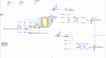
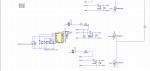
I am currently working on the design of a Wireless Power Transfer (WPT) system for an EV Charger. I am at the phase of simulating and validating the primary-side inverter driver stage before integrating the full resonant tank and secondary side.
I am using the UCC21520 isolated gate driver in LTspice, but I am facing persistent simulation stability issues that are blocking me from moving to the next phase of the project.
The Setup:
- Application: EV Wireless Charger (Primary Inverter Stage).
- Driver: UCC21520 (Isolated Dual-Channel Gate Driver).
- Simulator: LTspice.
- Current Phase: Standalone validation of the Gate Driver circuit.
- D3 & D7 Dependence: When the circuit is complete, I get no output. If I remove diodes D3 and D7, I get output only on the positive cycle (Low-side works, but High-side fails/floats).
- Intermittent Success: On one specific occasion, the simulation ran perfectly without any circuit changes. I have not been able to reproduce this successful run since.
My Questions:
- Are there known convergence issues with the UCC21520 model in LTspice for high-frequency WPT applications?
- Could the "random" success indicate an Initial Operating Point issue?
- Do D3/D7 require specific parameters (e.g., ultra-fast recovery vs. standard) to satisfy this specific driver model?
Any insights would be appreciated to help me get past this driver validation phase.
Thanks,
Attachments
-
 35.7 KB Views: 1
 -
 33.4 KB Views: 1