Facebook
 Google
 GitHub
 Linkedin
Discharger for Ultra-Capacitor Modules and Assemblies
This article introduces Innovation Plus Power Systems' Discharger Family for ultra-capacitor modules and assemblies, reducing the discharge time.
Ultra-capacitor modules and assemblies are increasing in use for many industrial applications. This has provided many advancements to customer’s applications but also challenges for use and service. Specifically discharging of these modules and assemblies has created a need to reduce discharge time for safe handling of storage systems for companies. Innovation Plus Power Systems USA, a Maxwell Certified Integrator, has introduced a family of fast dischargers to address these needs.
Principle of Operation
Typical discharging of an ultra-capacitor assembly is done with constant resistance using a power resistor, heatsink, and two-wire connection. For a fairly high starting voltage this can be a long duration until discharged to a low enough voltage for application of a shorting strap and safe handling, taking hours or even overnight. The Innovation Plus USA dischargers use five resistance levels switched at specific percentages of rated voltage to discharge systems or modules to final discharge completion of 1 volt.
The discharger family is designed to dissipate 1000W at rated voltage, 1200W at 110% of rated voltage. Each unit has simple front panel features:
- DC circuit breaker/switch to disconnect and protect discharger
- On/Off momentary switch
- AC Power On/Off switch for fan, control and display circuitry
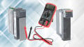
- DMM panel jacks for monitoring ultra-capacitor assembly voltage
- LED display for operating status
Discharger Features
The Discharger family consists of 8 units designed for different voltage levels. The voltage ratings with discharge rate (100% rated voltage to 1V) and maximum current are as follows:
- IPA-UCD25010 - 250VDC, 82 second per farad, 10A maximum
- IPA-UCD16010 - 160VDC, 32 second per farad, 10A maximum
- IPA-UCD125013 - 125VDC, 19 second per farad, 13A maximum
- IPA-UCD10016 - 100VDC, 12 second per farad, 16A maximum
- IPA-UCD08020 - 80VDC, 8 second per farad, 20A maximum
- IPA-UCD06025 - 60VDC, 5 second per farad, 25A maximum
- IPA-UCD04830 - 48VDC, 3 second per farad, 30A maximum
- IPA-UCD02030 - 20VDC, 1 second per farad, 30A maximum
The voltage ratings were chosen to optimize discharge time for each voltage rating while utilizing many common components. Higher voltage rated units can be used for a broader range of applications.
All units have a voltage withstand of +/- 300 VDC and isolated from chassis ground. Front panel LEDs will report faults:
- Reverse voltage - blocking rectifier is used to prevent damage
- Overvoltage – voltage above 110% of unit rating
- Overtemperature – unit will cease discharging until heatsink below thermal limit The input voltage range for operating the fan, control and display circuitry is 100 – 240 VAC and 50-60 Hz.
Thermal management of the discharger is provided by high CFM fan and power module heatsinks can we change to high capacity extruded heatsinks. The fan operation is temperature-controlled to turn-on at a pre-set temperature to reduce noise and extend fan life. Output cables are twist-lock connection 8 AWG, 600 Volt, flexible in Red and Black. Custom mating connectors can be applied to customer end to mate to their module or system. The unit is designed for use in the lab or field and weighs 40 pounds. Internal PC boards are conformal coated. The size of the unit is 11 inches wide by 9-1/4” tall by 16-1/4” long.
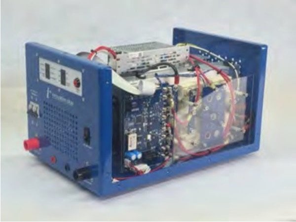
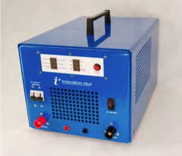
Figure 1: The Innovation Plus USA dischargers
Applications
The Discharger is designed to be used for production testing of systems utilizing ultra-capacitor technology or field service work for field personnel. Also individual module testing may be performed with the discharger for production or fieldwork.
An example application for sizing would be discharging the Maxwell BMOD0165P048, 165F, 48V module. The 48V discharger can be used (or higher voltage rated discharger). 30A maximum discharge current will result in less than 15 degrees C thermal rise within the module – very low thermal rise. 48V discharger will discharge up to 52.8V, which is below the 51V absolute maximum rating of the module. This should be above the 51V absolute maximum rating 165F x 3 sec/F = 8.25 minutes for discharge from 48V to 1V.
Conclusion
The Innovation Plus USA Discharger is built to provide companies a solution for reliable and safe discharging of ultra-capacitor modules and systems. The five resistance level discharging saves companies time in production as well as field service work. The unit is customizable for output connectors to make an easy transition to their system or production needs. Display features keep the user informed of system status and access to safe handling of the ultra-capacitors.
About Innovation Plus Power Systems
Innovation Plus Power Systems Inc. is part of a larger group of companies that have a primary focus on providing power electronic products and solutions to the industrial electronics industry. Engineering, design, and support is coupled with the largest inventory of power electronic components.
This article originally appeared in the Bodo’s Power Systems magazine.