Facebook
 Google
 GitHub
 Linkedin
Active Motor Simulation for Testing Automotive Inverters
This article highlights testing inverters that require a battery simulation and a motor simulation.
One of the central components of electrical or hybrid vehicles is the inverter – the device that converts DC voltage from the battery into AC currents for the electrical motor. Thus, testing inverters requires basically a battery simulation and a motor simulation. Battery simulations are available on the market. Depending on the parameters, either standard power supplies with or without grid feedback or specific powerful battery simulations may be applied.
To simulate the motor there are usually two options: simple passive load or a full-size motor simulator. The passive coil solution is very common in all fields of test in production, validation, and laboratory equipment. It is cost-efficient, simple, but with the drawbacks mentioned in the table below. Low DC current has the advantage, that relatively small power supplies can be applied, but the DC-path of the inverter is not tested under real conditions.

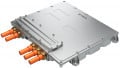
Figure 1: IRS Motor Emulator
| Passive coil | Active motor simulator – full size |
Active motor simulator - IRS |
| + Very cost-efficient | - Very high price | +/- Cost efficient |
| + Small setup | - Space consuming setup | + Small setup |
| + Full phase current | + Full phase current | + Full phase current |
| - Only reactive phase current | + Simulation of real phase currents | + Simulation of real phase currents |
| - No recuperation | + Recuperation possible | + Recuperation possible |
| +/- Low DC currents |
+/- Real DC current from battery |
+ Real DC current, but low power |
For Electronic motor simulations, the assortment is much more limited. For high power inverters with more than 100kW, highly sophisticated motor simulators are available from only few companies at prices well over 500.000 EUR. For many applications, the functionality of these simulators is oversized, e.g. in production lines or lifetime tests. In the latter, several inverters must be tested in parallel, resulting in the need of many motor simulations. Thus, in lifetime tests usually the simple coil solution is applied. IRS provides a cost-efficient motor simulation, where real currents are simulated including realistic battery current and where recuperation is possible. But still the current drawn from the battery simulator has only to cover the losses of the system.
The motor simulator is applied in several lifetime testers, EOL testers and LV124/GS95024 validation systems. The system is designed and produced by IRS. As in many other projects, the components for handling high currents and high voltages are provided by GvA, the partner of IRS for high power
Technical Description
The following picture shows the basic setup of the IRS electrical motor emulator for a three-phase-inverter as a device under test (DUT): The concept is based on the idea to directly run two inverters against each other - both three phases and the DC-Link are directly coupled.
As a battery simulator, a standard power supply may be used. With appropriate control of the motor simulator, the phase current flows from DUT to simulator via the phase coils and back to the DUT via the DC-Link, and vice versa. Thus, the DC-Link is stressed with a realistic current, but since the energy is flowing between the two inverters, the battery simulation has only to provide the energy for the losses of the entire system. This is one of the most important benefits: a relatively small power supply without energy feedback to the grid can be used. With a power supply of only 20kW, motors of about 250kW can be simulated.
As battery simulator a standard power supply may be used. With appropriate control of the motor simulator, the phase current flows from DUT to simulator via the phase coils and back to the DUT via the DC-Link, and vice versa. Thus, the DC-Link is stressed with a realistic current, but since the energy is flowing between the two inverters, the battery simulation has only to provide the energy for the losses of the entire system. This is one of the most important benefits: a relatively small power supply without energy feedback to the grid can be used. With a power supply of only 20kW, motors of about 250kW can be simulated.

Figure 2: Active motor simulator concept
In most setups, the simulator generates the induced voltage of the motor and the DUT is in current control mode, defining the applied torque to the motor.
Since the setup is symmetrical, either the DUT operates as generator and the simulator as motor load, or vice versa. Thus, both standard motor operation and recuperation can be simulated. Three phase currents and the negative DC-current of the DUT are shown in the figure. In this case, negative current means recuperation.

Figure 3: Typical phase currents and HV-DC current
Advantages and constraints Compared to the highly sophisticated motor simulators, where usually huge multi-level-inverters are applied, this setup uses a compact two-level inverter. This saves both space and cost to a great extent. Furthermore, the relatively small power supply benefits to low cost and size immensely.
Of course, there are constraints. The direct coupling needs good synchronization between the two inverters. The system runs best at fixed frequencies in the range of 5…10kHz. This chopping frequency also defines the maximum speed to simulate with a two-level-inverter. Furthermore, harmonics must be compensated with this direct coupling. A typical maximum frequency of phase current is in the range of 200Hz – at a 3-pole-motor leading to 4000RPM.
The focus of IRS motor simulator are applications, where fixed operating points are selected, rather than simulation of a full non-linear motor model. Linear motor models can be implemented.
But many applications do not need to simulate the full speed range or mechanical behavior of the motor. Thus, IRS motor simulator is the best choice in applications where speed and motor harmonics are not crucial, but space and cost determine the best fitting simulator system. Please note, that both cost and space savings – compared to highly sophisticated simulators - exceed the factor of 10 by far!
On the other hand, the simulator only needs about twice as much space compared to a simple passive coil solution
Position sensor simulation
To test an inverter, not only the load for the motor phases has to be simulated. The inverter needs to know the exact motor position to apply the appropriate current on the respective phases. IRS provides two versions of position sensors: ·
AMR/GMR position sensor (for e.g. Infineon TLE5309) · Resolver-simulation. Both variants are integrated in the motor emulator. Furthermore, they are also available as Compact-RIO or stand-alone module IRS Sens- Sim or IRS Resolversimulation, when a simple inductive coil solution is applied.
Both variants are integrated in the motor emulator. Furthermore, they are also available as Compact-RIO or stand-alone module IRS Sens- Sim or IRS Resolversimulation, when a simple inductive coil solution is applied.

Figure 4: 6-Phase motor simulation
6-Phase motor simulation
Powerful electrical vehicles may apply 6-Phase motors in the future. This means twice the power and the motor may continue working even with a phase failure. Two IRS motor simulator can be combined and synchronized to simulate a 6-phase motor. This setup already proofs its reliability in several test stations at the customer.
Independent DUT voltage
When the DUT HV voltage should be flexible and independent from the Emulator, Both DUT and Emulator may be supplied with separate power supplies. This can be useful e.g. for LV123 tests, where different HV-voltages must be applied at the DUT, while the motor simulator performs at the same setpoint. This setup is feasible with IRS motor simulator, but of course, will require larger power supplies, including grid feedback.

Figure 5: Power devices from GvA
Technical Data
| Min | Typ | Max | Unit | |
| HV-DC voltage range | 30 | 1000 | V | |
| Phase Current (Typ=continuous / max=for 60 seconds) |
500 | 700 | ARMS | |
| Peak phase current (overcurrent protection) |
-1000 | 1000 | Apk | |
| Phase inductance (may be modified application specific) |
85 | μH | ||
| Phase current frequency | 0 | 200 | Hz | |
| Inverter chopping frequency | 4 | 8 | 14 | kHz |
This article originally appeared in Bodo’s Power Systems magazine.
About the Author
Michael Rost is the Project Manager at IRS Systementwicklung GmbH