 Facebook
 Google
 GitHub
 Linkedin
Resistor Applications
Resistors are used in a wide variety of applications. This chapter of the Resistor Guide contains pages explaining various resistor applications.
Resistors in Series
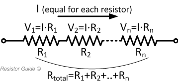
In a series connection of resistors, the same current flows through each resistor as there is only one path for the current to flow. The voltage drop is proportional to the resistance of each individual resistor. The total resistance of the connection is represented as:
$$R_{eq} = \sum_{i=1}^n R_i = R_1 + R_2 + \dots + R_n$$
Resistors in Parallel
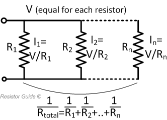
In a parallel connection of resistors, the voltage across each resistor is equal. The current however, is proportional to the resistance of each resistor. Total resistance is represented as:
$$\frac{1}{R_{eq}} = \sum_{i=1}^n \frac{1}{R_i} = \frac{1}{R_1} + \frac{1}{R_2} + \dots + \frac{1}{R_n}$$
Heater Resistor
Heater resistors are used when an electronic device needs to generate heat. They are specially designed types of resistors that can provide a reliable and controllable heat.
A heating resistor can create a convective heat, as it heats up the surrounding air, or radiant heat, making it heat up other objects through infrared radiation. Radiant heating requires the heater resistor to be placed within the line of sight of the object that is to be heated. Using a fan to blow air across heater resistors increases the heating effectiveness.
Current Limiting Resistor
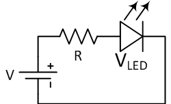
A current limiting resistor is a resistor used to reduce the current present in a circuit. A simple example is a resistor in series with an LED to limit the current control through it. This can set the intensity of the light generated and prevent the LED from exceeding its current limit and burning out.
To calculate the resistance value of the resistor to be used, it is represented by:
$$R = \frac{V - V_{LED}}{I}$$
Where V is the source voltage VLED is the LED voltage and I is the LED current.
Pull-up and Pull-down Resistors
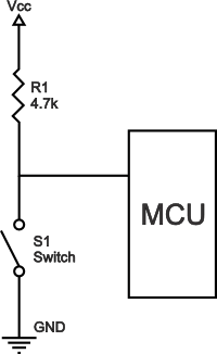
Pull-up resistors are resistors commonly used in logic circuits to help ensure a well-defined logical level at a pin under all conditions. It is used to prevent the logic state to be left as “floating". The pull-up resistor solves this problem by pulling the value to a logical high state when switch S1 is open instead of leaving it floating.
Pull-up resistors are not a special kind of resistor. They are simply fixed-value resistors connected between the voltage supply and the appropriate pin to define the input or output voltage in the absence of a driving signal.
Pull-down resistors work in a similar manner as pull-up resistors, except that they pull the pin to a logical low value. They are connected between ground and an appropriate pin on the device.
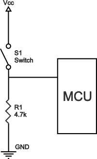
An example of a pull-down resistor used in a digital circuit can be seen in the figure above. Switch S1 is connected between the supply voltage and a microcontroller pin. When the switch is closed in the said circuit, the microcontroller input is at a logical high value, but when the switch is open, the pull-down resistor will pull the input voltage down to ground (logical zero), preventing an undefined state.
Pull-up and pull-down resistors must have a larger resistance than the impedance of the logic circuit. If the resistance is too low, the input voltage at the pin will remain at a constant logical value independent of the switch position.