Facebook
 Google
 GitHub
 Linkedin
Advancing EVs With Chip Embedding and Driver Tech
This article features the electrical results obtained by a half-bridge board, which synergistically combines three technologies–Infineon’s CoolSiC Gen2p technology, Infineon’s new generation EiceDRIVER, and packaging technology from Schweizer Electronic AG–to fully harness the potential of each component.
This article is published by EE Power as part of an exclusive digital content partnership with Bodo’s Power Systems.
Infineon’s 1200 V CoolSiC Gen2p is a cutting-edge power semiconductor technology that offers significant advancements in efficiency and performance. The technology is designed to meet the demanding requirements of automotive 800 V power applications, especially the main inverter. It comes with outstanding Rds,onA, over the whole temperature range by further reducing the cell pitch and adjusting the drift zone of Infineon’s trench cell concept. Due to the low on-state resistance and its low switching losses, the Gen2p provides excellent light-load efficiency, which is a major factor for range gain and potential system-level cost savings. [1]
S-Cell in Smart p2 Pack Technology
To leverage the full potential of CoolSiC, the 100 percent electrically tested standard cell (S-Cell) depicted in Figure 1 is embedded into the Smart p2 Pack of Schweizer Electronic AG [2]. This printed circuit board technology is already in production for 48 V starter generator applications, thereby increasing performance by up to 60 percent in comparison with conventional solutions [3, 4]. The Smart p2 Pack features a thermally conductive, electrically insulating layer to ease system design. The embedding of 1200 V MOSFETs marks a leap forward in high-voltage packaging technology, harnessing the full potential of the CoolSiC technology by providing:
- High design flexibility to meet different power and geometry constraints
- Minimized stray inductance enabling clean and fast switching for high-efficiency power conversion
- High level of system integration

Figure 1. The Smart p2 Pack of Schweizer Electronic AG integrates Infineon’s S-Cell 1200 V CoolSiC Gen2p chips into the PCB, increasing performance by up to 60 percent in comparison with conventional solutions. Image used courtesy of Bodo’s Power Systems [PDF]
3rd Generation EiceDRIVER
The gate driver 1EDI3035AS is Infineon’s novel automotive inverter gate driver in a compact 20-pin DSO package. It is specifically designed to provide the highest degree of compatibility with silicon carbide technologies by optimizing the internal supervision thresholds and timings without the need for the user to control a complicated SPI programming interface.
The output stage delivers up to 20 A peak current and is prepared to drive multiple SiC cells in parallel. It is capable of driving state-of-the-art inverters beyond 300 kW power rating. To accommodate for the best trade-off in short circuit performance vs. efficiency, an ultra-fast SOFTOFF concept is implemented, which is freely tunable by means of an external SOFTOFF resistor.
The driver status and several internal diagnostic functions can be read back through a simple PWM-coded DATA interface, making this gate driver ideal for rapid prototyping and shortening development timelines.
Chip Embedding Board
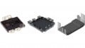
In Figure 2, the designed chip embedding board is depicted. It consists of five connectors to the main DC link capacitor while also having three 900 V CeraLink capacitors close to the MOSFET half-bridge acting as local DC link capacitors in order to minimize stray inductance. Each switch consists of one embedded S-Cell with a 20 mm² CoolSiC chip. The close positioning of the gate driver to the half-bridge and the single-board design allows for a low inductive gate connection, fast switching, and low oscillations. The gate driver supply is not shown; it is attached to the power board via the SMD pin headers. It provides a bipolar supply voltage to the secondary side of the driver as well as supplying the primary side. The board is engineered to enable thorough electrical measurements and therefore features five coaxial surface mount connectors (SMA and MMCX) for voltage measurements, as shown in the schematic depicted in Figure 3. This avoids unwanted magnetic coupling into the probe leads. The current is measured via a network of parallelized SMD shunt resistors leading to high measurement bandwidth.

Figure 2. Smart p2 Pack demonstrator board with 1200 V CoolSiC and 3rd generation EiceDRIVER. Image used courtesy of Bodo’s Power Systems [PDF]

Figure 3. Schematic of the demonstrator board’s power loop. Image used courtesy of Bodo’s Power Systems [PDF]
Double Pulse Measurements
In Figure 4, a recorded turn-off waveform can be seen. The board was operated at room temperature with a turn-off resistance of 10 Ω and a DC link voltage of 800 V. The switched-off current is 114 A. The top graph shows the measured drain current id,ls and drain-source voltage vds,ls of the low-side MOSFET. The lower graph depicts the gate-source voltage vgs,ls. The gate voltage shows a very smooth shape, first discharging the input capacitance. Then as the drain-source voltage starts to rise, the miller plateau can be seen. The current reduction in this phase is due to the discharging of the high-side MOSFET during the voltage rise of vds,ls. After forward biasing the high-side body diode the current decreases rapidly. Due to the low inductive design (~2nH) of the switching cell, the magnitude of voltage overshoot is minimal. Also, ringing is very low to reach EMI targets in the drivetrain. With the demonstrator board, measurements of up to 100 V/ns (turn-off) and 28 A/ ns (diode turn-off) are performed, showing no inherent limitations.

Figure 4. Exemplary recorded turn-off waveform. Image used courtesy of Bodo’s Power Systems [PDF]
Short Circuit Measurements and DESAT Detection
The designed measurement board is also used to test the short circuit behavior of the 1200 V CoolSiC Gen2p under very low-inductive and fast-switching applications. As the shunt resistor cannot withstand the high pulse energy in a short circuit event, it is removed and replaced with a copper sheet. This copper sheet is soldered to the pads of the shunt resistor so that a Rogowski coil can be used. The 3rd generation EiceDRIVER features very low blanking (ideal for SiC), detection and reaction times for the inbuilt DESAT functionality. Measured waveforms can be seen in Figure 5. The top figure shows the current for different desaturation capacitors, while the middle and bottom graphs show the drain-source voltage and gate-source voltage. Following a very fast current rise of 55 A/ns (Rg,on,ext = 0 Ω) the current saturates at around 1200 A. Subsequently, the self-heating effect can be seen, leading to a reduced saturation current before turning off the MOSFET via the SOFTOFF pin. It takes the driver only 456 ns after the turn-on (VEE+1.5 V) of the driver stage to detect and react (VCC -1.5 V) to the short circuit event. A minimum short circuit time of 549 ns (according to [5]) is reached, showing the striking performance of the combination of an Infineon EiceDRIVER with an embedded solution. Despite high peak power, the energy reached with the setup is far below the destruction energy of the chip.

Figure 5. Short circuit type 1 waveforms. Image used courtesy of Bodo’s Power Systems [PDF]
Conclusion
This article showcases the electrical results obtained by a half-bridge board, which synergistically combines three technologies–Infineon’s CoolSiC Gen2p technology, Infineon’s new generation EiceDRIVER, and packaging technology from Schweizer Electronic AG–to fully harness the potential of each component. It enables voltage transients of up to 100 V/ns, low oscillations, low voltage overshoots, as well as a short circuit time of <550 ns.
References
[1] D. Meichsner, T. Anthony, B. Rosam, C. Schweikert and M. Leitner , “Performance and Feature Benchmarking of SiC Trench Technologies and Cooling Systems for DSC Modules in Traction Inverters,” in PCIM Europe 2023: International Exhibition and Conference for Power Electronics, Intelligent Motion, Renewable Energy and Energy Management, Nuremberg, Germany, 2023.
[2] Schweizer Electronic AG, “p2 Pack Embedding,” [Online]. Available: https://schweizer.ag/technologien-loesungen/leiterplatten-technologien/halbleiter-embedding-systeme/p2-pack. [Accessed July 2023].
[3] Infineon Technologies AG, „Infineon und SCHWEIZER vertiefen Zusammenarbeit im Chip-Embedding für effizientere Siliziumkarbid-Lösungen im Automotive-Bereich,“ 26 April 2023. [Online]. Available: https://www.infineon.com/cms/de/aboutinfineon/press/market-news/2023/INFATV202304-093.html. [Accessed July 2023].
[4] N. Flaherty, eeNews Power, “Embedded MOSFET boost for 48V powertrain designs,” May 2019. [Online]. Available: https:// www.eenewseurope.com/en/embedded-mosfet-boostfor-48v-powertrain-designs/. [Accessed July 2023].
[5] European Center for Power Electronics e.V., “ECPE Guideline AQG 324 Qualification of Power Modules for Use in Power Electronics Converter Units in Motor Vehicles,” 2019.
This article originally appeared in Bodo’s Power Systems [PDF] magazine and is co-authored by M. Ippisch, product application engineer of high-voltage inverters and M. Weinmann, senior product application engineer of automotive gate drivers, both of Infineon Technologies.