 Facebook
 Google
 GitHub
 Linkedin
Passive And Active Electronic Components
Power in AC Systems
In a previous page, we discussed phasors, but we didn’t explore the full significance of phasor techniques with regard to AC circuit analysis. The fundamental point to understand is the following: by representing circuit quantities using complex numbers, we make it possible to analyze an AC circuit as though it is a DC circuit.
From Resistance to Impedance
We already know that currents and voltages in an AC circuit can be written as phasors, i.e., as a magnitude (corresponding to the peak value of the sinusoidal waveform) accompanied by an angle (corresponding to the phase difference between the sinusoidal waveform and a reference waveform). A phasor can also be written as a complex number consisting of a real part and an imaginary part.
In the case of currents and voltages, the magnitude-plus-angle representation is more intuitive. The real-plus-imaginary representation, however, is useful for an additional and very important application of phasors: representing impedance.
In a basic DC circuit, we have DC voltages, DC currents, and resistances. In an AC circuit, we have AC voltages, AC currents, and impedances. An impedance indicates a component’s opposition to current flow, just as resistance does, but it also conveys the phase shift associated with the component. Another way of explaining this is as follows: A resistance establishes the relationship between the magnitude of the voltage across a component and the magnitude of the current flowing through the component. An impedance establishes the relationship between the magnitude of the voltage and current as well as the phase difference between the voltage and current.
Impedance is written as a complex number and denoted by the letter Z, and in the context of circuit analysis impedance values are completely equivalent to resistances. This means that the analysis techniques that we use for DC circuits can be applied directly to AC circuits if we represent the components as impedances and the currents and voltages as phasors.
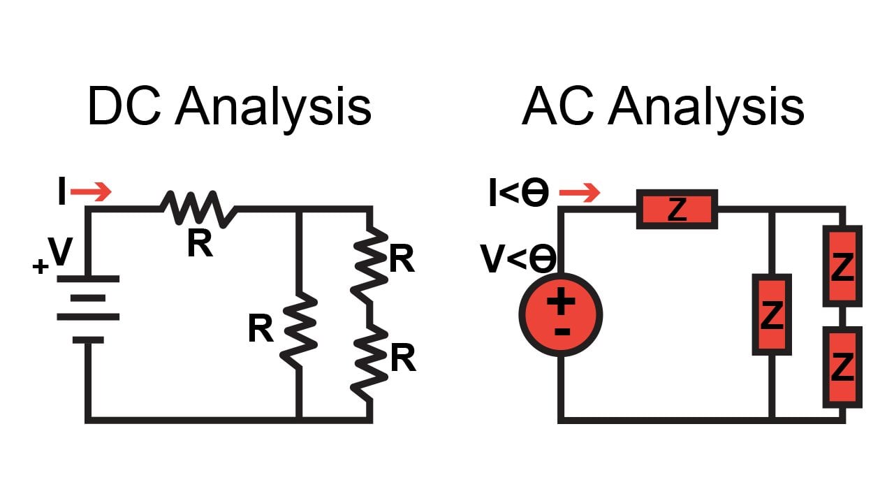
Figure 1. Phasor notation and the concept of impedance allow us to analyze AC circuits as if they are DC circuits (the math in AC analysis is often more complicated, though).
The Impedance of Passive Components
At this point we know that a component can be represented as an impedance, but what exactly is the impedance of a resistor, capacitor, or inductor?
For the resistor, it’s easy: the impedance is equal to the resistance.
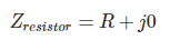
Normally we wouldn’t need to write “j0”; in this case, it’s included to emphasize the fact that resistance is purely real and, consequently, the impedance of a resistor has no imaginary part.
The impedance of a capacitor and inductor are expressed as follows:
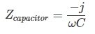
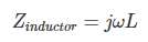
As you might recall, ω stands for angular frequency and is equal to 2π times the “normal” frequency (i.e., the frequency measured in cycles per second). Also, the unit attached to these expressions is ohms. Resistance, reactance, and impedance all convey information about resistance to current flow, and they all use the same unit.
The following sections discuss some very important information that is wrapped up in these equations.
Frequency Response
In the expression for capacitive impedance, the ω term is in the denominator of the impedance formula. In the expression for inductive impedance, the inductance is multiplied by the ω term. These relationships reveal the fundamental behavior of capacitors and inductors in the context of AC circuits: capacitors provide less opposition to current flow as frequency increases, and inductors provide more opposition to current flow as frequency increases. This is why we use capacitors to block the DC component of a signal and inductors to suppress high-frequency noise.
Resistance and Reactance
The real part of an impedance indicates the amount of resistance, and the imaginary part indicates the amount of reactance. A resistor is a purely resistive component, and thus its impedance has only a real part. Capacitors and inductors, on the other hand, are purely reactive components, and as you can see, for both of these components the entire impedance expression is multiplied by j, meaning that the impedance has only an imaginary part.
Power Dissipation and Phase Shift
The real part of impedance corresponds to the portion of a component or circuit that creates power dissipation, and the imaginary part corresponds to the portion that creates a phase difference between voltage and current. A purely imaginary impedance (i.e., a reactance) will not dissipate any power, and a purely real impedance (i.e., a resistance) will not produce any phase shift.
These statements are consistent with the expressions shown above: A resistor’s impedance has no reactance; all of the current passing through a resistor contributes to power dissipation, and the current remains in phase with the voltage. The impedance of a capacitor or inductor has reactance but no resistance; these components store energy rather than release it into the surrounding environment, and they create a phase difference between current and voltage.
Capacitive and Inductive Phase Shift
We know that capacitors and inductors affect the phase relationship between voltage and current, but what exactly is the phase shift that they introduce?
We can find the phase shift of a complex impedance by using the polar form instead of the real and imaginary parts; the angle of the polar-form representation is the phase shift. In general, this angle is calculated using the arctan function, but in this case, we will simply look at the impedance in the complex plane:
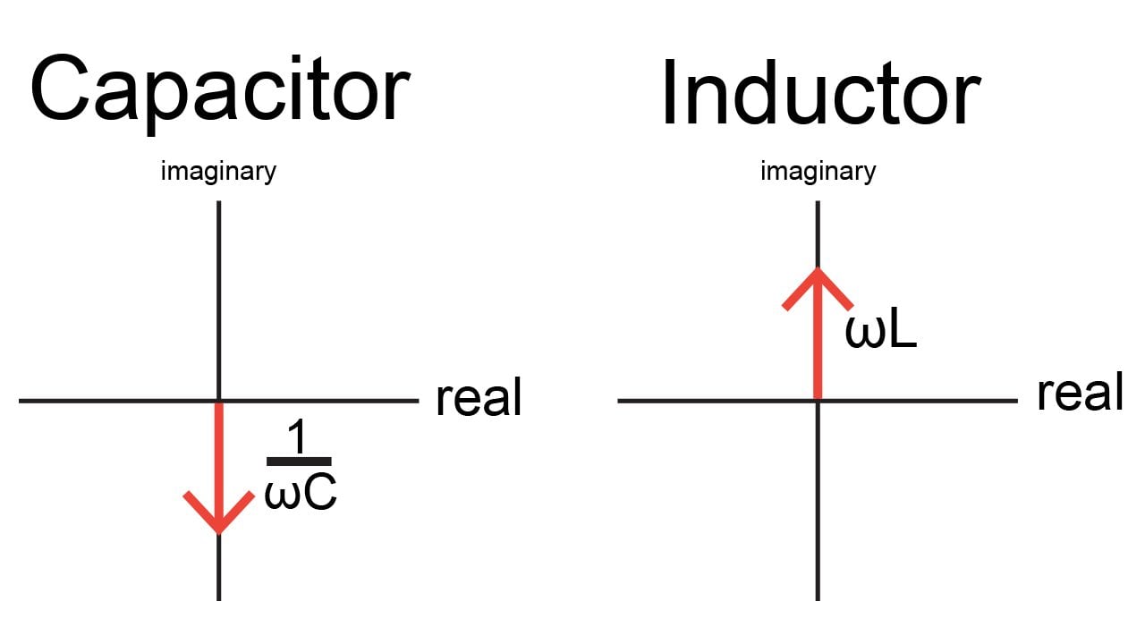
Figure 2. The vectors represent the (purely imaginary) impedance of a capacitor and inductor.
Capacitive impedance extends along the negative imaginary axis, which corresponds to an angle of –90°; inductive impedance extends along the positive imaginary axis, which corresponds to an angle of +90°. Thus, both capacitors and inductors introduce a 90° phase difference between voltage and current.
To understand the meaning of the positive and negative signs, consider the following: To calculate a voltage using Ohm’s law, we multiply current by resistance. If we extend this into the domain of AC circuits, we multiply the phasor representing a current by the impedance of a component.
When we multiply polar-form complex numbers, we have to add the angle values. We know that the angle of a capacitor’s impedance is –90° and the angle of an inductor’s impedance is +90°. Thus, the voltage across a capacitor will have a phase equal to the phase of the current minus 90°, and the voltage across an inductor will have a phase equal to the phase of the current plus 90°. This is consistent with what we learned earlier in this chapter: in a capacitive circuit, voltage lags current; in an inductive circuit, voltage leads current.
Next: Power in Reactive Circuits
We have explored important information related to impedance, which is a fundamental concept that appears frequently in the design of various types of electrical systems. In the next page, we’ll look at some additional details related to power in reactive circuits.