 Facebook
 Google
 GitHub
 Linkedin
Importance Of Maximum Power Transfer
Impedance Matching and Power Transfer
This page explores the issue of how to design a system that will efficiently transfer power from source to load. First, though, we need to discuss two parameters that govern the interaction between portions of a circuit.
Understanding Input Impedance and Output Impedance
A common technique used in engineering is to separate a system into smaller interconnected subsystems. In the context of electrical engineering, we can divide a circuit into multiple subcircuits and then perform our analysis based on input impedance and output impedance.
The input impedance of a circuit is the impedance that it presents to another circuit that is providing an input signal. In other words, the input impedance tells us how much the input current will change for a given change in input voltage.
The output impedance of a circuit is the impedance that it presents to the circuit that will receive the output signal. This means that the output impedance indicates how much the circuit’s output voltage will change for a given change in the amount of current that must be supplied by the output circuitry.
A simple example will help to reinforce these important concepts. Let’s say that we have a voltage source with a high output impedance, and it’s connected to an amplifier circuit with a low input impedance. This is a problematic arrangement:
- The high output impedance of the source means that changes in output current will create relatively large changes in output voltage.
- The low input impedance of the amplifier means that any change in input voltage will create a relatively large change in input current.
- Thus, the two subcircuits are working against each other. Our goal is to transfer the original voltage signal from the source to the amplifier, but the signal received by the amplifier will be greatly attenuated—the amplifier draws large amounts of input current, and this current must be supplied by the source, which exhibits large changes in voltage in response to changes in supplied current.
The following plot shows the original waveform (i.e., the waveform before it is affected by the source’s output impedance) and the output waveform for a circuit composed of a unity-gain amplifier and a component that generates a sinusoidal signal (let’s say that it’s a sensor of some kind). The sensor has an output impedance of 100 Ω, and the amplifier has an input impedance of 10 Ω.
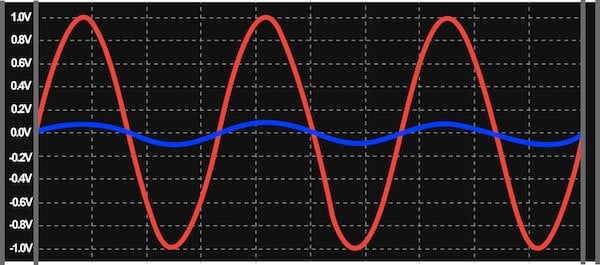
Figure 1. The effect of combining a high-output-impedance voltage source with a low-input-impedance amplifier. The orange trace is the original waveform, and the blue trace is the output of the amplifier.
Maximum Voltage Transfer
The serious loss of signal amplitude in Figure 1 demonstrates why designers very frequently attempt to reduce output impedance and increase input impedance.
When your goal is to transfer a voltage signal from one subcircuit to another—i.e., when you want maximum voltage transfer—remember the following: the subcircuit supplying the signal should have low output impedance so that changes in supplied current do not seriously affect the output voltage, and the subcircuit receiving the signal should have high input impedance so that changes in received voltage do not cause large changes in input current.
An important point to keep in mind when you’re pondering the preceding sentence is that we’re using different words to identify the same quantities because we’re discussing these quantities from two different perspectives. From the perspective of the source circuit, we have output voltage and supplied current. From the perspective of the load circuit, we have received voltage and input current. Nevertheless, the source’s output voltage is the same as the load’s received voltage, and the load’s input current is the same as the source’s supplied current.
If we take the example circuit discussed above and switch the input and output impedances, we obtain the following waveforms:
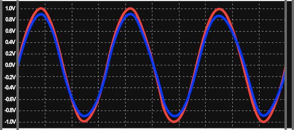
Figure 2. The amplifier’s output voltage (blue) is now only slightly lower in amplitude than the original signal (orange), because the source’s output impedance (10 Ω) is much smaller than the load’s input impedance (100 Ω).
Maximum Power Transfer
It turns out that we must take a different approach to input and output impedance when the goal is to maximize the transfer of power, rather than voltage, from source to load.
In the context of resistive circuits, maximum power transfer occurs when the input impedance of the load is equal to the output impedance of the source.
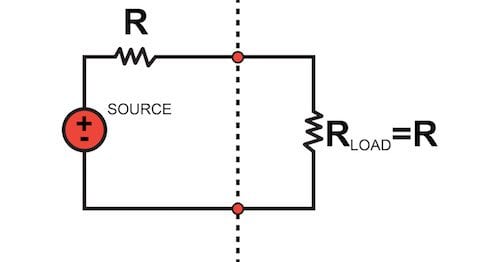
Figure 3. Maximum power transfer in a DC system.
We won’t examine the mathematical derivation of this fact, but it makes basic sense if we consider it from an intuitive perspective.
When input impedance is large and output impedance is small, voltage is transferred effectively but current flow is restricted by the large input impedance. If we make the input impedance much smaller than the output impedance in order to increase current flow, the amplitude of the received voltage is reduced.
Since power is calculated as voltage times current, a very small voltage or a very small current will result in low power. Thus, to maximize power transfer we need to seek balance, i.e., an impedance relationship that allows for moderate voltage transfer and moderate current flow. This is achieved by making the input impedance of the load equal to the output impedance of the source.
In the context of AC systems involving both resistance and reactance, maximum transfer of active power is achieved when the load’s input impedance is the complex conjugate of the source’s output impedance. The term “complex conjugate” refers to complex numbers that have identical real parts and imaginary parts that are equal in magnitude but opposite in sign. Thus, the source will transfer maximum power to the load when the load’s resistance is equal to the source’s resistance and the load’s reactance has the same magnitude as the source’s reactance but the opposite sign.

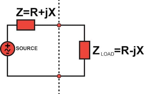
Figure 4. Maximum power transfer in an AC system.
Choosing Source Impedance vs. Choosing Load Impedance
As current flows through the source’s output impedance, power is dissipated rather than delivered to the load. It seems, then, that maximum power transfer would occur when the source impedance is zero rather than equal to the load impedance.
Actually, that is exactly the case. If it is possible to change the source impedance, maximum power transfer occurs when the source impedance is zero. The requirements for maximum power transfer described above assume that the source impedance cannot be changed.
It is very important to understand this distinction—setting load impedance equal to source impedance (or the complex conjugate of source impedance) is a way to achieve maximum power transfer with respect to a given source circuit. If the load impedance is fixed and the source impedance is variable, we can increase power transfer simply by reducing the source impedance.
Maximum Power Transfer and Transformers
The process of designing for maximum power transfer is often described as impedance matching, particularly in the context of radio-frequency systems, where matched impedances maximize transmission power and prevent signal reflections.
In the previous page, we saw that transformers can change the impedance of a load connected to the secondary winding if we analyze the load component from the perspective of a voltage source on the primary side. Now that we have discussed impedance matching, we can better understand why this property is valuable. Sometimes there are practical constraints that make it difficult to match impedances simply by choosing load components, and in such cases, it might be possible to use a transformer with the appropriate turns ratio to match the load impedance to the source impedance.