- Network Sites:
-
 EEPower Day is a free 1-day virtual conference. Learn More
We already know that purely reactive components (or purely reactive circuits) do not dissipate power. We also know that a purely reactive impedance has an angle of +90° or –90°. How are these two facts related? Well, consider the following plot:
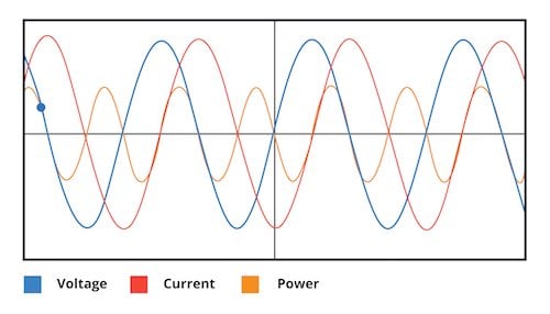
Figure 1. Graphical representation of the relationship between voltage, current, and power.
The voltage and current are out of phase by 90°. The power waveform shows the result of multiplying current and voltage. As you can see, multiplying two sinusoids that have a phase difference of 90° results in a sinusoid that is positive for half of each cycle and negative for half of each cycle. This indicates that no power is dissipated because all the power delivered to the system (during one half of the AC cycle) is returned to the source (during the other half of the cycle).
In Figure 1, the voltage waveform reaches its maximum value before the current waveform. In other words, voltage is leading current, which means that the plot corresponds to an inductive circuit. The plot for a capacitive circuit would have current leading voltage, but the overall result (with regard to power) would be the same: the average value of the power waveform would be zero, indicating the transfer of energy to and from the source but no actual dissipation of power.
This is the last page in Chapter 1. We will conclude this chapter with a summary of information that will be particularly important as you continue your study of sinusoidal power in Chapter 2. It’s essential to develop a thorough understanding of how reactive circuitry interacts with current and voltage and how it affects power. This really is the essence of AC power analysis, because purely resistive circuits are very straightforward and because inductance and capacitance are extremely common in real-life systems.
A sinusoidal voltage and current is a constantly varying quantity that has amplitude (which is related to the maximum value of the waveform), frequency (measured as cycles per second or radians per second), and phase (which identifies the temporal position of the waveform relative to another waveform).
There are two ways to specify the amplitude of a sinusoidal signal. The peak value (which could also be called the amplitude or the magnitude) corresponds to the largest distance between the horizontal axis and any point along the waveform. RMS amplitude is equal to the peak value divided by the square root of 2; it is frequently used because it provides a simple way to calculate average power dissipation in AC circuits.
Sinusoidal currents and voltages can be represented as phasors, which are complex numbers consisting of a magnitude and an angle. It is possible to use peak value or RMS amplitude as the magnitude of a phasor, and the angle of a phasor is equal to the signal’s phase shift relative to a “zero-phase” reference signal.
These three words all refer to circuit elements that oppose current flow. Resistance leads to power dissipation, reactance leads to phase shift between voltage and current, and impedance refers to any opposition to current flow, whether it is resistance, reactance, or a combination of the two. When a circuit contains both resistive and reactive elements, the impedance is a complex number in which the real part corresponds to resistance and the imaginary part corresponds to reactance. An AC circuit consisting of impedances and phasors representing current and voltage can be analyzed as though it is a DC circuit consisting of resistances and DC currents and voltages.
These are called reactive components. They have only reactance; in other words, their impedance has only an imaginary part. Capacitors create a delay in voltage relative to current; thus, in a capacitive circuit, current leads voltage. Inductors create a delay in current relative to voltage; thus, in an inductive circuit, voltage leads current.
Capacitors and inductors have an important effect on power systems. By creating a phase difference between voltage and current, these components lead to reactive power, which refers to power that is delivered by the source but not consumed by the load. Instead, this power corresponds to energy that is temporarily stored by reactive elements and then returned to the source. Active power, in contrast, is dissipated by the load circuitry.
This quantity conveys information about the proportions of active and reactive power required by an AC system. A higher proportion of reactive power is generally considered undesirable because this reduces the efficiency of transferring AC power from source to load.