A Low-Profile IPM with Optimized Heat Dissipation for Use in Restricted Environments CIPOS Nano IPM
This article introduces the Infineon's CIPOS Nano IPM that functions in space-constrained environments by dissipating heat via PCB.
In the modern world, some applications are placed in space-constrained environments; for example, a motor with an embedded PCB. As a result of the limited space, there is no airflow and no room to apply additional cooling, such as a heatsink.
Restricted Environments Need an Innovative Approach
Products used in these applications need to have sufficient thermal margin and be able to effectively dissipate the excess heat due to power losses within the increased ambient temperatures that occur during operation.
In this article, we will introduce the CIPOS™ Nano IPM that functions in space-constrained environments by dissipating heat via the PCB.
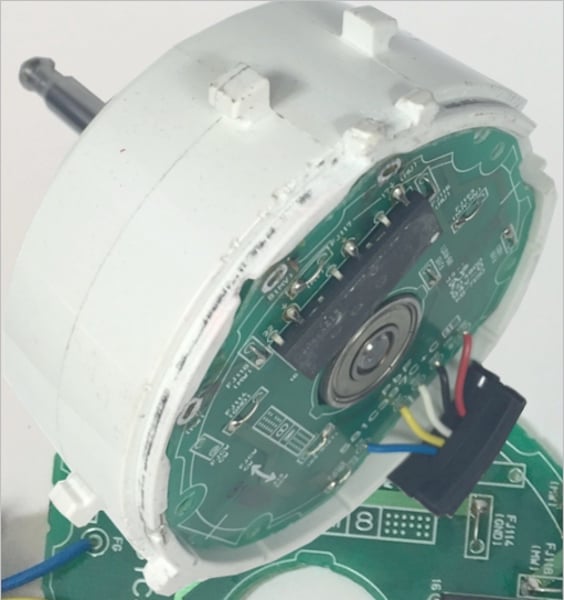
Figure 1: Example of a restricted environment where the PCB is mounted inside the motor
Single-Phase 220 V AC Applications
Some small motors have the PCB mounted inside the motor body itself. This is typical for motors used in applications such as air conditioning, ceiling fans, air purifiers or ventilation, as shown in Figure 2. In these applications, the rated motor power ranges from 40-60 W.

Figure 2: Examples of typical applications for a 40-60 W motor
These applications often operate with the motor running with very little or no air to dissipate heat by means of convection. Therefore, thermal dissipation will be conducted through the surface of the PCB. When an IPM is used in a space-restricted environment, the thermal calculations must be performed carefully.
Figure 3(a) shows how the heat from power FETs is dissipated through the PCB. The design of the Intelligent Power Modules (IPM) ensures that the lead frame attached to the FETs directly contacts the PCB, allowing generated heat to be dissipated directly through the PCB.
Infineon's small 3-phase CIPOS Nano IPM (12 x 12 x 0.9 mm) was selected for its thermal dissipation characteristics. This family of IPMs comprises a six-channel gate driver and six MOSFETs in a single package (as shown in Figure 3(b)).
The 500 V CIPOS™ Nano parts can be used for 220 VAC motor drive applications due to VDC being around 311 V. The IPM offers overcurrent protection and its fault clear time can be determined by setting R and C values.
Figure 3(c) demonstrates an application circuit for a sensorless motor drive circuit that includes an Infineon IRMCF171 appliance motion control IC. In this circuit example, the IPM’s fault pin is connected to the GATEKILL pin of the IRMCF171 allowing the controller to shut down all gate signals whenever a fault occurs.

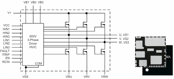
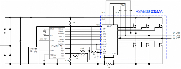
Figure 3: (a) The Nano IPM dissipates heat directly via the PCB (b) The Nano IPM in a 12 mm x 12 mm PQFN package (c) Application circuit example
Power Capacity Measured by a Thermal Test
As mentioned above, the heat from the Nano IPM is dissipated via the PCB together with its thermal conductivity. However, this requires verification by thermal measurement. Figure 4(a) shows the PCB layout and the results of thermal measurement conducted with a thermal camera. This CIPOS™ Nano IPM on a PCB, with 1 oz. copper traces at an ambient temperature of 25℃ with no airflow can run a motor with an output current of 500 mA using discontinuous Space Vector PWM (SVPWM) operation. In three-phase SVPWM operation, the IPM can handle output currents up to 480 mA. In this case, the switching frequency is 6 kHz and the electrical power output to the motor is around 65 W as shown in Figure 4(b).

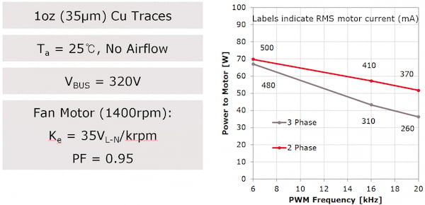
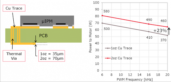
Figure 4: (a) PCB layout and thermal camera measurement result (b) Max. motor power on 1 oz. copper PCB traces (c) Increased motor power on 2 oz. copper PCB traces
When using a 2 oz. copper PCB, more current can be delivered. For a switching frequency of 6 kHz, the IPM can increase current capacity from 500 mA to 580 mA; representing an increase of 16%. If the switching frequency is 20 kHz, current capacity can be increased from 370 mA to 460 mA - a 23% increase.
For greater current capacity, the isolated thermal film can be applied directly to the PCB.
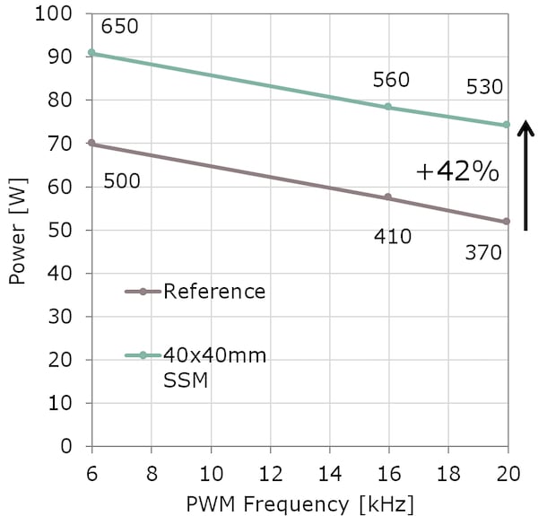
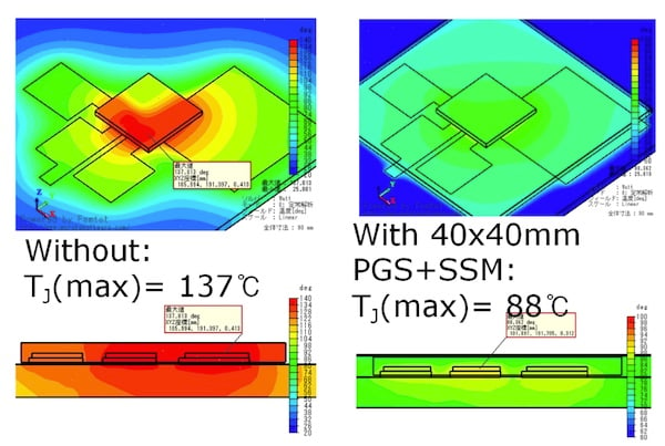
Figure 5: (a) Max. power with isolated thermal film, PGS+SSM (b) Using the film reduces junction temperature from 137℃ to 88℃
When 40 x 40 mm isolated thermal film was applied, the junction temperature reduced from 137℃ to 88℃ as seen in Figure 5(b). At a switching frequency of 6 kHz, current capacity can be increased from 500 mA to 650 mA, a 30% increase. For switching frequencies of 20 kHz, current capacity can be increased from 370 mA to 530 mA, an increase of 42%.
Low-Voltage Fan or Battery-Driven Motor Application
Some motor applications require a low-voltage fan rated under 100 V DC in which this fan is operated by a DC voltage of 24 V or 48 V, or a battery voltage under 60 V. For this type of application, a low-voltage IPM, such as the 40 V, 80 A, IRSM005-800MA or the 100 V, 30 A, IRSM005-301MA half-bridge CIPOS Nano IPM is needed. The mechanical design concept for these IPMs is the same as the 3-phase Nano IPM. Similar to the devices mentioned earlier, these devices also have direct thermal contact between the lead frame and the package surface (and, therefore, the PCB).


Figure 6. (a) Low voltage Nano IPM in a 7 x 8 mm PQFN package (40 V or 80 A half bridge IPM & 100 V 30 A IPM) (b) Application circuit with bootstrap diode, capacitor & gate resistor
Designing with IRSM005 IPMs simply requires an addition of a bootstrap diode, capacitor and gate resistor. These IPMs are suitable for single-phase applications, h-bridge or 3-phase applications by choosing different half-bridge configurations with the CIPOS devices.
Conclusion
In this article, we have shown that a motor application with embedded PCB in a space-restricted environment needs a proven solution that overcomes the lack of airflow and heatsink. System design demands an adequate thermal margin that must be calculated and measured, using a thermal camera or other technique.
About the Authors
Simon Kim works at the Infineon Technologies, South Korea, Seoul, a branch of the German multinational company, Infineon Technologies. They offer semiconductor and system solutions addressing three central challenges to modern society: energy efficiency, communications, and security.
Pengwei Sun is a Staff Engineer, Technical Marketing and Applications at Infineon Technologies, El Segundo, C.A. He is in-charge of Electrical design of IPM schematics and layout. He earned both his Bachelor's Degree in Electrical Engineering and Master's Degree in Power Electronics and Motor Drive, Electrical Engineering at North China Electric Power University. He also took his Doctor of Philosophy (Ph.D.), Power Electronics, Electrical Engineering at Virginia Polytechnic Institute and State University.
Danish Khatri is the Principal Engineer at Infineon Technologies Americas Corp., in charge of identifying new business opportunities; driving product development in collaboration with technology, manufacturing and project management teams. He earned his Bachelor's and Master's Degree in Electrical Engineering at Massachusetts Institute of Technology, Massachusetts, USA.
References
- IRSM836-035MA, 3 Phase Nano IPM (500 V 3 A IPM) datasheet
- IRSM005-800MA, half-bridge Nano IPM (40 V 80 A IPM) datasheet
- IRSM005-301MA, half-bridge Nano IPM (100 V 30 A IPM) datasheet
- IPM Presentation File
- Application Note AN-1168