IPM Solution for Low Rated Power Application
This article proposed and discussed the thermal and circuit benefits of a low rated power application without heat-sink approach using 600V 4A µIPM-DIP.
“Energy saving” is applied to all power electrical systems and low rated power application is no exception to this. It can be realized to move forward, from no-inverter design to inverter design. In addition, the lightweight and compact size are always a concern for the product design. No heat-sink approach is in the trend. In this article, no heat-sink IPM solution with µIPM-DIP is introduced.
Home Appliances for Market Needs
To further reduce the energy consumption, consumer market requests to speed up the interiorization. It is no exception to home appliances. Especially, home appliances with low rated power are also falling in the range gradually. Home appliance makers try to make the product smaller and lighter. With these considerations, no heat-sink approach for appliances can be in the trend. Therefore, no heat-sink Intelligent Power Modules (IPM) solution is introduced with some application specifications.
Low Rated Power Application
The definition of low rated power can be different for each application field. In this document, the rated power application under 150W is reviewed with some application in the home appliance. Here, fan and fridge compressor under 150W can be considered with the following specifications (refer to Table1).
Table 1: Target specification for fan & fridge compressor
For these targeted specifications, IPM solution is considered as a fast and easy solution.
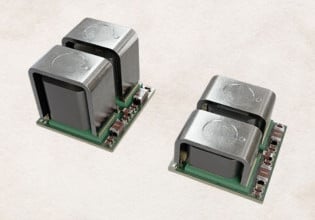
The 600V 3A IPM can be considered for under 150W application, however, for both no heatsink approach and higher frequency applications (around 15[kHz]), 3A cannot be a proper solution. Hence, 600V 4A ~ 6A can be good candidates. Infineon µIPM-DIP 4A module’s plastic body dimension is “29 x 12 x 2.9[mm]” and 3 package types can be supplied to customers: SOP23, DIP23 & DIP23A.
Figure 1: µIPM-DIP 600A 4A IPM package (top) & its application example circuit (bottom)
Figure 1 (bottom) shows a sensor-less motor drive circuit example with Micom, IRMCF171. µIPM-DIP is composed of a gate driver, IGBT, and NTC. By adding the bootstrap capacitor, IGBT can be operated from the controller due to embedded bootstrap diode simply. Also, this IPM has open emitter type in each leg and it makes easier for the developer chooses between one- shunt and three-shunt solutions. The 3.3V controller is compatible with this IPM. By using embedded NTC in µIPM-DIP, this module can be protected by a thermal comparator. In the example circuit, external thermal comparing with 3V reference voltage allows the controller to be aware of the NTC temperature inside of IPM around 115[℃]. In no heat-sink condition and steady status, this NTC value matches estimated junction temperature, 135[℃] (refer to [1]). If the developer wants to set a lower thermal protection level, the reference level can be set in another value. In addition, NTC terminal from IPM inside is connected to a controller and the controller monitors its value directly.
Fan Application in Air Conditioning System
Thermal result for estimated 130W fan application can be expected from Figure 2. This shows “carrier frequency vs RMS phase current” accompany with fixed junction temperature. This graph was made and based on thermal tests in air condition. The test was done with two different control modulations, such as 3-phase & 2-phase modulations. The junction temperature was monitored by an IR camera and controlled around TJ=128°C. Estimated 130W fan is operated in fs/w = 15[kHz] & Iout = 460[mA] in Table 1. Figure 2 shows that 530[mA] is achievable in 15[kHz] around TJ=128[°C]. So, in air condition operation for an estimated 130W fan, this IPM’s junction temperature can be lower than TJ=128[°C].

Figure 2. Max phase current vs carrier frequency, no heat-sink. Space Vector Modulation, V+=320V, TA=28°C, TJ=128°C
To estimate junction temperature accompany with targeted customer operation conditions, Infineon IPM simulation tool can be supported as online simulation [2]. Especially, no heat-sink simulation is possible. First, the user should select “No heatsink needed”. Put TA=28°C in Reference temperature and 0.53[A] in “Motor driver phase current RMS”. Then, put the value in “thermal resistance (case to reference)” and adjust this value to simulation results in TJ=128°C. In this case, this value would be around 30.5[k/w]. This value is high due to no heat-sink condition and highly depends on customers’ PCB design. With “thermal resistance (case to reference)” value, the maximum junction temperature for a 130W fan without heatsink operation can be calculated in Ta = 45[℃] and the value would be around 132[℃] (Refer to Figure 3.). It is in the thermal safe area.
Figure 3. Expected simulation result for 130W fan with 15[kHz]
Fridge Compressor Applications
In addition, 80W Fridge compressor application particularly in appliances can be reviewed with Figure 4.
Figure 4. Max phase current vs carrier frequency, no heat- sink. Space Vector Modulation, V+=320V, TA=28°C, TJ=98°C
Estimated thermal result for 80W fridge can be calculated by Infineon simulation tool. In Ta = 50 [℃], the estimated max junction temperature is around 113[℃]. It is in the thermal safe area as well.
For system safety, short circuit capability must be reviewed and tested. In this test, AC line and (-) terminal were in common by wire and then one pulse was applied on Top IGBT in Infineon µIPM-DIP 4A module. Test condition was with Vdc = 400[V] and Isc = 20[A] for 5[µs]. The IPM was passed without any failure (Refer to Figure 5).
Figure 5. Test board & Test circuit with u-IPM-Dip(Top) and Test graph for short circuit test in Vdc = 400[V] & Isc = 20[A] peak(bottom)
For short circuit or overcurrent protection, the controller does monitoring the voltage on shunt in software protection. In addition for hardware protection, an external comparator can be applied with some voltage reference level (current trip level).
Additional Solutions
If the customer wants to use IPM with error feedback to a controller, Infineon suggests CIPOS Tiny (Refer to Figure 6).
Figure 6: CIPOS tiny’s body dimension(top) and it circuit example with Error feedback
Conclusion
In this article, for low rated power applications under 150W without heat-sink approach, 600V 4A µIPM-DIP was proposed. It showed good short circuit capability and thermal margin with both applications such as 130W Fan and 80W Fridge compressor applications. For Error Feedback from IPM to the controller, CIPOS Tiny can be a solution.
About the Author
Simon Kim works at the Infineon Technologies, South Korea, Seoul, a branch of the German multinational company, Infineon Technologies. They offer semiconductor and system solutions addressing three central challenges to modern society: energy efficiency, communications, and security.
Pengwei Sun is a Staff Engineer, Technical Marketing and Applications at Infineon Technologies, El Segundo, C.A. He is in-charge of Electrical design of IPM schematics and layout. He earned both his Bachelor's Degree in Electrical Engineering and Master's Degree in Power Electronics and Motor Drive, Electrical Engineering at North China Electric Power University. He also took his Doctor of Philosophy (Ph.D.), Power Electronics, Electrical Engineering at Virginia Polytechnic Institute and State University.
Reference
- IRSM506-076, uIPM-DIP (600V 4A IPM) data sheet
- Web Infineon IPM Motor Drive Simulator: https://plex.infineon.com/plexim/ipmmotor.html
- IRAM363-066EA, CIPOS Tiny (600V 6A IPM) data sheet
This article originally appeared in the Bodo’s Power Systems magazine.


![Expected simulation result for 130W fan with 15[kHz]](https://eepower.com/uploads/thumbnails/894-5021-infineon.jpg)

![Test board & Test circuit with u-IPM-Dip(Top) and Test graph for short circuit test in Vdc = 400[V] & Isc = 20[A] peak(bottom)](https://eepower.com/uploads/thumbnails/894-5023-infineon.jpg)


