Configurable Gate Drives for nHPD2
This article discusses a flexible approach to gate drive designs using nHPD2 package from Hitachi targeted at traction applications.
The nHPD2 package targeted at traction applications offers a number of advantages for the power stack designer, but also adds complexity in designing a gate drive that can be used to target the different options offered by the nHPD2 package. The article describes a flexible approach to the gate drive design.
Introduction
The nHPD2 package from Hitachi offers a number of advantages for the power stack designer, but some of these advantages provide challenges for the design of the associated gate drive. A flexible approach to the design of the gate driver will enable the power stack designer to optimize the design quickly.
The nHPD2 Package
The nHPD2 module is designed to meet the future challenges and requirements of power converter design. An enabler for scalable, optimized converter designs, it offers reduced losses, enhanced monitoring and a simple route to oscillation-free Silicon Carbide (SiC) adoption.
The product range offers a standardised package throughout the industrial voltage classes (1700 V to 6500 V) with simple paralleling for high currents. This allows a modular, scalable converter design with a high level of design re-use across platforms to keep client system costs low.
The very low stray inductance, offering a 75% reduction compared to IHM modules, permits optimized converter design. Paired with the latest generation Hitachi IGBT silicon, nHPD2 offers low losses and high power density, while future adoption of SiC is straightforward and available today.
Protection and monitoring is enhanced through the inclusion of an NTC temperature sensor and current measurement via auxiliary terminals.

Figure 1: LV and HV nHPD2
Challenges for the Gate Drive Design
The nHPD2 package is a very compact design, which is highly challenging for a complete gate drive to be fitted on top of the package. The situation becomes easier if multiple nHPD2 packages are placed in parallel, as the additional space can be used to mount the whole gate drive close to the IGBT module package. Customers, who prefer to mount the gate drive away from the IGBT module, for reasons of reliability or survivability in the event of a major failure, or to keep gate drive electronics cooler, can split the gate drive design, with protection circuits mounted on top of the IGBT module package and the core gate drive mounted away from the package.
The nHPD2 is designed to be paralleled, but the difficulty for the gate drive designer is that the spacing between IGBT modules may be different for each power stack design. A flexible approach would be to use cables to connect the paralleled IGBT modules together, but this would require using many connectors; in high-reliability applications, this may not always be acceptable. The alternative is to use a fixed printed circuit board as a distribution board. This has the advantage of robustness and simplicity, but does mean that each parallel design would require a new design of distribution board.
Parallel connection of IGBT modules brings its own challenges. The layout of the bus bars and the gate inductance can have a large effect on the current sharing between the individual IGBT modules. There is no substitute for good design practice. Nevertheless, the nHPD2 package minimizes the impact of parallel imbalance.
The nHPD2 package is also designed to support SiC devices, given that it has a very low stray inductance. In this way, the faster switching speed of SiC MOSFETs, which significantly reduces switching losses, is not impeded by having to limit voltage overshoots to such an extent at turn-off. The gate drive can be designed to be compatible, but the high dV/dt of the SiC power devices requires that the power supply for the gate drive will also need updating.

Figure 2: Modular Gate Drive Concept
Modular Gate Drive for Fast Evaluation
The flexibility of the nHPD2 package design dictates a flexible gate driver for initial evaluation and power stack design testing. Amantys Power Electronics has split up the main functions of the gate drive to make it easier to customize the design for a particular power stack.
The concept is shown in Figure 2 for three nHPD2 modules in parallel. The core gate drive contains all of the standard features of the gate drive, such as the gate resistors and control of the gate drive protection features.
The module interface card (MIC) is mounted directly on top of the nHPD2 module. This contains the desaturation detection circuit and the measurement circuits used by Amantys. Care needs to be taken to ensure that creepage and clearance distances between adjacent nHPD2 modules will meet the specified standards even if the nHPD2 modules are mounted very close to each other.
Amantys has used a simple distribution card to connect the paralleled nHPD2 modules together. This does mean that the design has to be changed if the module spacing changes. However, by keeping the distribution card simple, this task will be relatively straightforward. Finally, the interfaces and power supplies are mounted on a separate card above the distribution board. The power supply and the interfaces to the central controller are very dependent on the layout of the converter and the voltage. The option of using an electrical or fibre optic interface is easily accommodated.
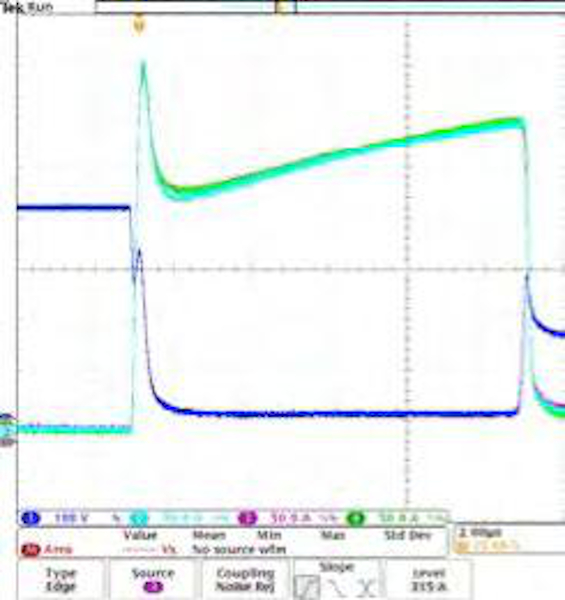
Figure 3: Parallel Performance of three nHPD2 Modules
Parallel Switching Performance
The nHPD2 is designed to be paralleled easily. Nevertheless, good layout design rules for the bus bars and the DC link capacitors still need to be followed. The impedance of each current path through the paralleled IGBTs must be as closely matched as possible. This is sometimes difficult to achieve and the addition of a common mode choke on the emitter and the gate can help to match the current flow through the IGBT modules. Figure 3 below shows excellent results using Amantys’ nHPD2 gate drive with three nHPD2 modules in parallel.
Gate Drive Optimization
Amantys’ gate drives feature Power Insight, which is a two-way communications protocol between the central controller and the gate drive. Data is superimposed on top of the PWM switching command and feedback/acknowledge signal. This allows online configurability of the gate drive; for example, the power stack designer can modify gate resistor values (Rg_on, Rg_off and Rg_soft_off) and gate-emitter capacitances (Cge) without removing the gate drives from the power stack or interrupting device switching. This opens the door to selection of gate resistances appropriate to different converter operating conditions, see Figure 4. This is of potential use in applications with varying DC link voltage, such as DC-fed rail traction applications (750 V, 1500 V, 3000 V) and solar inverter applications; it is also useful in renewable energy applications in allowing wider variation in DC link voltage under grid fault conditions, simplifying controller design. The Amantys core architecture provides the power stack designer with the ability to modify voltage detection levels and timings for desaturation detection. The interaction between the power stack and the gate drives can be fully optimized for maximum performance.
SiC Compatibility
Since the nHPD2 package is offered with full SiC options, Amantys has included a feature on the gate drive to enable -5 V off-state and +20 V on-state gate drive output voltages for evaluation of future full SiC modules, such as the full SiC module from Hitachi, MSM600FS33A. Additional future-proofing of the Amantys gate driver includes superior fast short circuit protection within 5 µs which is highly desirable for wide-band gap device operation.

Figure 4: Using selectable gate resistance to tune device switching to converter operating conditions
Vce(on) Measurement
The on-state voltage drop between the collector and emitter of the IGBT, Vce(on), is an important measurement for assessing the IGBT module operation and can be an input into algorithms for detecting degradation. The gate drive includes a high-resolution Vce(on) measurement circuit on the module interface card that can be read from the gate drive over the Power Insight link using a Power Insight Adapter.
Conclusion
The nHPD2 module offers a significant step forward in improving the performance of the power stack. The ease of paralleling the nHPD2 module makes it simple to build a flexible power stack to target a wide range of applications. Supporting this new generation package technology, Amantys has designed a flexible, configurable gate drive, providing outstanding current sharing across multiple nHPD2 modules that enables the power stack designer to evaluate quickly and then optimize the performance of the power stack.
About the Authors
Bryn Parry works as a General Manager at Amantys Power Electronics Ltd., Cambridge, United Kingdom. He is a senior-level executive with considerable experience in the semiconductor, software and intellectual property sector. Experienced in marketing, business development, team development and operations. He earned his Bachelor's Degree in Engineering Physics at Loughborough University located in Loughborough, England.
Chris White was formerly the Product Marketing Manager of the Power Device Division at Hitachi Europe. After promotion, he now works as the Engineering Manager of the Power Device Division started last April 2019. Chris earned his Master of Engineering in Electrical and Electronics Engineering at Cambridge University located in United Kingdom.
This article originally appeared in the Bodo’s Power Systems magazine.