Everything for Capacitive Power Supplies from a Single Source
This article emphasizes the importance of capacitors and their capacitive properties and topologies in the designs of power supplies.
Designs based on capacitive topologies are particularly suitable for power supplies in the milliwatt range. They are simple, compact and economical. In addition to the capacitors – and therefore the key components – TDK offers almost all the other passive components for these designs.
Development engineers are faced with the task of supplying a growing number of devices and system units that only have low voltages and currents in the milliampere range. Typical examples are displays for measurement data or timers, microcontroller-based measuring systems and simple open- and closed-loop controls. Similar challenges are presented when devices have to be connected to wireless networks – for example, in the case of smart meters whose readings are taken wirelessly, or network-operated devices for the Internet of Things.
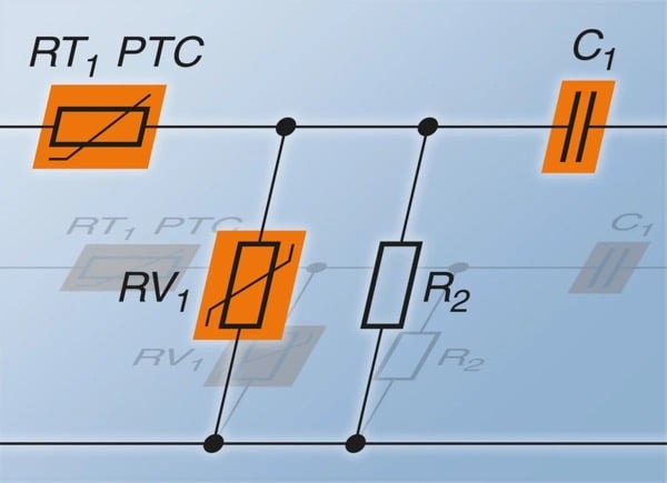
Figure 0: Capacitive power supplies
Conventional power supply designs have a number of disadvantages in the very low power range. Solutions with transformers or switched circuits require a lot of space and are expensive. In addition, the copper and iron losses are disproportionately high in relation to the low output. Although the simplest solution – the line-side connection of an ohmic resistor – is inexpensive, it does generate high losses and thus opposes the high efficiency rates required.
Exploiting the reactance of capacitors to practical effect
One possibility for supplying small loads from the AC power supply that is not only elegant, but also simple and cost-effective, is to connect the capacitor and load in series. This makes use of the otherwise unwanted effect of phase shift: The voltage arrives at a capacitor with a 90-degree phase shift from the current; the capacitor acts as a reactive power, at which practically no actual losses occur. A capacitor used as a series resistor is therefore the ideal solution. Figure 1 shows the circuit diagram as well as the associated vector diagram of the voltages. In contrast to conventional designs, the capacitive power supplies are short-circuit-proof at the output.
As the capacitor is directly connected to the power supply, very high demands are made on its reliability. It is therefore recommended that only X2 capacitors compliant with UL and ENEC are used for capacitive power supplies.
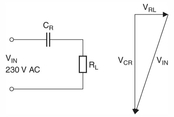
Figure 1: Circuit diagram of a capacitive power supply. The vector diagram makes it clear: The majority of the input voltage drops out at the reactance of the capacitor with virtually no power dissipation being created in the capacitor.
For this purpose, TDK offers a wide range of EPCOS X2 capacitors such as the new B3292*H/J* series. To permit reliable operation with stable capacitance values, even under extreme climatic conditions such as high temperatures in combination with high humidity, the X2 Heavy-Duty Series (B32932* through B32936*) was developed. These components show a capacitance drift of no more than 10 percent in a 1000-hour test at 85°C and 85 percent relative humidity. There is one more advantage of these capacitors: they are self-healing. This means that smaller disruptive discharges result in a locally limited vaporization of the metallization without creating a short circuit and therefore retaining the function of the capacitor.
Calculation of a capacitive power supply
In practice, the power supplies most in demand are those that provide a DC voltage at the output. The simplest solution is in single pulse rectification as shown in Figure 2; for the calculation example, an output voltage of around 9 V DC is generated at a maximum load current of 15 mA.
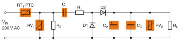
Figure 2: Simple capacitive power supply
For the function of a Zener diode: During the positive half-wave, D1 operates as a voltage-limiting component. In order to achieve the required output voltage of 9 V, the Zener’s voltage would have to be 9.7 V, because about 0.7 V drops off at D2. However, as no Zener diodes with this value are available, a diode with a value of 10 V and a maximum power dissipation of 1.3 W is chosen. If the power supply switches on at the line voltage peak, an inadmissibly high current would flow through D1, resulting in its destruction. To limit the current therefore, R1 is connected on the line side. As a rule, Zener diodes with a power dissipation of 1.3 W can manage momentary currents of about 1 A. This enables the value of R1 to be calculated as follows:
`R_1=((230\ "V")*(sqrt(2)))/(1\ "A")="325.27"\ \Omega`
The nearest standard value is 330 Ω. In operation, R1 is continuously subjected to the entire load current. To calculate this, the ratio of ACRMS to the DC average value must be taken into consideration. As this involves single pulse rectification, the form factor is 2.22. With the required 15 mA output current this produces a current through R1 of 33.3 mA and consequently a power dissipation of:
`P=(33.3\ "mA")^2*(330\ \Omega)=0.366\ "W"`
A resistor is chosen with a load capacity of 0.5 W. The voltage drop through this resistor is almost 11 V.
From the data determined thus far, it is now possible to calculate the necessary reactance of capacitor C1. In order to guarantee a reliable supply of the load even when there is an undervoltage, the calculation should be performed with a voltage drop of at least 10 percent; in addition, the voltage drop via R1 and D1 must to be taken into consideration. This produces the reactance as follows:
`XC_1=(230\ "V"-23\ "V"-11\ "V"-10\ "V")/(33.3\ "mA")=5585.6\ \Omega`
From this it is possible to calculate the necessary capacitance at the normal line frequency of 50 Hz:
`C_1=1/(2\pi*50\ "Hz"*5585.6\ \Omega)=0.57\ \mu"F"`
Consequently, the next standard value is a capacitance of 0.68 µF. Depending on the climatic conditions this means, for example, that the EPCOS X2 capacitor type B32933A3684K* from the heavy-duty series is suitable. This has a lead spacing of 22.5 mm and is designed for a voltage of 305 V ACRMS at a maximum permissible operating temperature of 105°C. Alternatively, one can use the B32923H3684K* type, which is even designed for up to 110°C, likewise with a lead spacing of 22.5 mm. Both types exhibit a capacitance tolerance of ±10%.
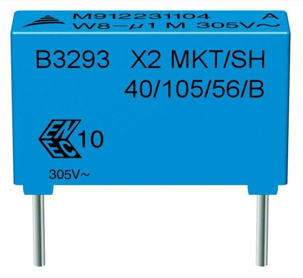
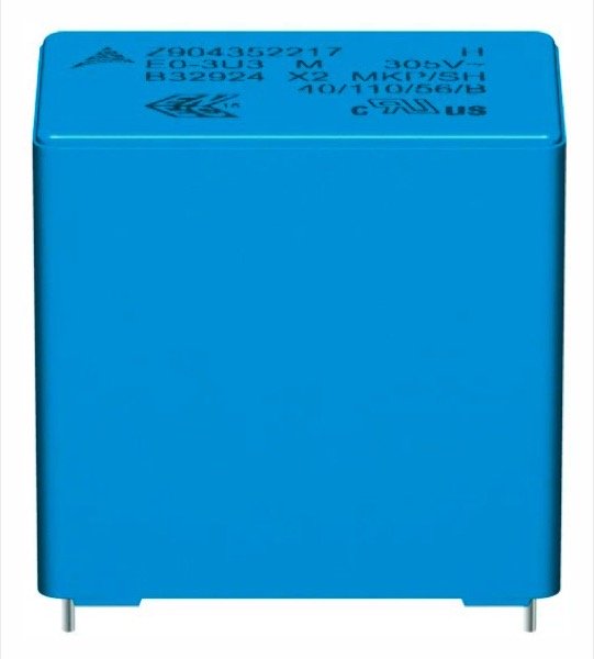
Figure 3: EPCOS capacitors for capacitive power supplies. Two typical EPCOS X2 capacitors that are suitable for capacitive power supplies: on the top a type from the heavy-duty series, and on the bottom a type from the B3292*H/J series.
The economical standard type 1N4001 (50 V, 1 A), designed for peak currents of up to 35 A, is sufficient for the diode D2 which ensures the single pulse reactance. This diode is offered by a number of semiconductor suppliers.
Secure supply through efficient smoothing
C2 is is responsible for smoothing the output voltage. As this is a one-pulse reactance, the entire output current of C2 must be made available during the negative half-wavelength. The necessary capacitance of this depends on the permissible ripple of the output voltage. For the circuit in the example, a maximum value of 1 V is required. At the maximum load current consumption of 15 mA at 9 V, a load resistance of 600 Ω is produced. With a line frequency of 50 Hz (10 ms per half-wavelength) the minimum capacitance of C2 can thus be determined:
`C_2=(-10\ "ms")/(600\ \Omega*ln((8\ "V")/(9\ "V")))=140\ \mu"F"`
A single-ended aluminum electrolyte capacitor is selected with a capacitance of 150 µF and a permissible voltage of 25 V DC. In order to achieve the longest possible life, this capacitor should be designed for a temperature of at least 105°C.
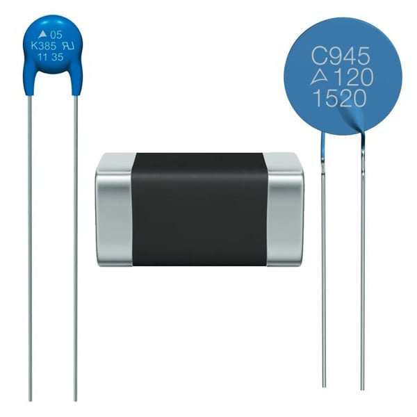
Figure 4: EPCOS protective component for power supplies. From top to bottom: Disk varistor for overvoltage protection at the power input and CeraDiode® for protecting the output, PTC for overcurrent protection at the power input.
Optionally, a ceramic capacitor (C3) can additionally be connected in parallel with C2. This is used for noise suppression and for blocking voltage peaks. For example, a TDK MLCC with a capacitance of 0.1 µF can be considered for this purpose. The type C1608X7R1E104K080AA was selected with a nominal voltage of 25 V DC with size 1608 (IEC) and X7R temperature characteristic (-55 to +125ºC, ±15%).
Circuit protection is essential
In a worst-case scenario it may happen that, when switching off without load, C1 remains charged with the peak voltage of 325 V. It is then the task of R2 to discharge the capacitor as quickly as possible. When setting the resistance value, a compromise must be made between power dissipation and discharge time constant. In this case the value of 470 kΩ was selected. A power dissipation of approx. 0.1 W occurs here and the discharge time to a maximum permissible touch voltage of 50 V takes around 0.5 s. If the power supply is continuously connected to the grid, however, there is no need for this resistor.
The overvoltage protection at the line input (RV1) is also important, of course. For this purpose, TDK offers various series of EPCOS varistors. The types from the EPCOS standard series are suitable for the stated circuit, as these cover a wide range of voltages from 11 VRMS to 1100 VRMS. These protection components are available with disk diameters of between 5 mm and 20 mm, corresponding to the re-quired surge current capability and energy absorption. In this case, for example, the compact type B72205S0231K101 with a disk diameter of 5 mm is suitable, which features a surge current capability of 400 A at a pulse of 8/20 µs.
In addition, the output of the circuit can also be protected against overvoltage (RV2), for example, using the EPCOS SMT CeraDiode® B72590D0150A060, which has a DC voltage of 15 V.
Finally, an EPCOS PTC B59873C0120A570 (RT1), which is designed for a maximum load current of 90 mA at 25°C, ensures the current limitation at the power input. If a fault should occur in the circuit that results in an increased current flow, the PTC heats up, causing its resistance to rise sharply and thus limit the current to non-critical values.
Thanks to the comprehensive range of TDK components, capacitive power supplies with other voltage and current values can be realized.
Bill of Material
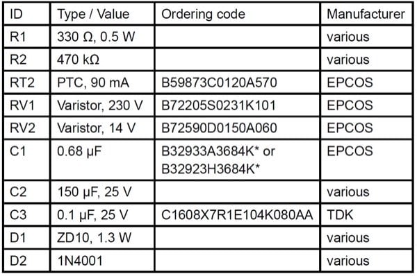
Table 1: Bill of Materials
About the Author
Christophe Jehle is the head of Products & Technologies at TDK Electronics, an electronics company based in München, Bayer, Germany that develops, manufactures and markets electronic components and systems, focusing on fast-growing leading-edge technology markets, which include automotive electronics, industrial electronics and consumer electronics as well as information and communications technology.