Utilizing SiC Traction Technology Inverters in Automotive Applications
This article focuses on presenting the benefits of a newly developed SiC power module and the utilization of this module in a powertrain inverter
In 2010, the first Silicon Carbide (SiC) power transistor was launched to the market. This initiated a revolution in the power electronics field and is leading to an increasing rate of SiC devices adoption in many industrial and automotive application fields which proved that SiC components are strong competitors to classical Si devices in such applications. Electric Vehicle (EV) applications represent a big potential area where the adoption of high-performance SiC power devices can provide benefits.
This article focuses on presenting the benefits of a newly developed SiC power module and the utilization of this module in a powertrain inverter. A comparison of the performance of the SiC-based inverter with a Si-based traction inverter is also shown in this article.
In motor traction inverter application requirements like space, weight, and efficiency play an increasing role. Product development and manufacturing expenses should remain low while the design efforts should result in more compact systems and, at the same time, product quality and reliability should be guaranteed. This leads to more demanding design requirements on the system and component levels and ultimately affects the overall system consisting of power devices, passive components, cooling technologies, and PCBs. In order to achieve the required enhanced system properties, semiconductor devices have to enable higher power density, higher efficiency, and reliability.
A simplified block diagram of a traction powertrain is shown in Figure 1. The use of SiC power devices in the powertrain inverter leads to an increase of the entire powertrain system efficiency and helps to miniaturize the system thanks to improved switching losses, conduction losses, and thermal conductivity. Therefore, it is expected to gain longer driving range with the same battery capacity or a substantial reduction of battery size and weight for the same driving range. In this way, the efficiency and weight improvements bring an economic benefit to the users.
Figure 1. Simplified EV traction inverter system
A Comparison Between IGBT Modules and SiC Modules
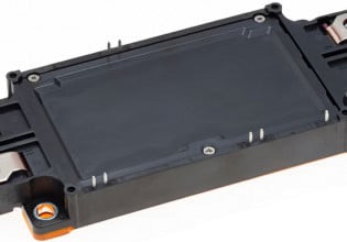
The new Gtype package module BSM600D12P3G001 from ROHM is used in this application (Figure 2). It is a half bridge module which utilizes the device technology of SiC Trench Gate MOSFET [1] [2] and Schottky Barrier Diode (SBD). Ten SiC MOSFET chips are used in parallel per switch. The rated DC drain current is 600A at Tc=50°C. In the next diagrams, a comparison between the Gtype module and two markets available latest generation IGBT modules with the same rated current is shown.
Figure 2. The new SiC module package Gtype
Figure 3 shows a comparison of output characteristics at a junction temperature of 150°C. In terms of conduction loss, the curves for SiC MOSFET and IGBT modules cross at around half of the rated current.
Figure 3. Output characteristic comparison between a Gtype module and two IGBT modules with same rated currents
A comparison of switching losses also at a junction temperature of 150°C is presented in Figure 4. As can be seen, the total switching losses of the Gtype module with SiC devices are ca. 65% lower than for the IGBT modules at the rated current of 600A. Due to the lower switching losses, the SiC module can be operated at a much higher switching frequency.
Figure 4. Switching losses comparison between a Gtype module and two IGBT modules with same rated currents
Traction Inverter
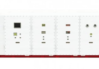
Figure 5 shows two traction inverters. The left-hand inverter is rated at 200kW and utilizes power modules with Si IGBTs and Si Fast Recovery Diodes (FRDs). This type of inverter has been available since 2013. The right-hand inverter was newly developed utilizing full SiC modules and is rated for 220kW. In addition to using SiC Trench Gate MOSFETs and SiC SBDs, a better concept of motor control strategy, an efficient cooling system, a low inductive busbar design, and a smaller DC link capacitor are successfully implemented. Both inverters are water-cooled systems and both designs can be used with up to 800V battery systems [3].
Figure 5. Two powertrain inverters (Si IGBT based 200kW inverter and SiC MOSFET based 220kW inverter)
Table 1 shows a specification comparison of both inverters. The new inverter utilizes variable switching frequency which can vary depending on the motor operating point from 16kHz to 24kHz. Even in the lower rotor shaft speed range, the inverter utilizes 16kHz switching frequency to avoid the risk of resonance between the DC link capacitor and input cables. While the available maximum output power is 20kW higher, the SiC MOSFET based inverter has lower volume and less weight than the Si IGBT based one. The weight is reduced by ca. 6kg and the volume is shrunk by 30% as well. These factors lead to a high power density inverter of 22kW/L, which is 57% higher than the conventional IGBT-based solution.
Table 1. Comparison of Inverters Parameters
Performance of the Inverters (Efficiency and Losses)
Figures 6 and 7 describe the inverter efficiency and power transistors losses over the rotor shaft speed and rotor torque in all operating points. For this efficiency and losses comparison, the operating profile based on the same motor design has been used to simply compare the performance.
Figure 6: Comparison of the inverter efficiency of both IGBT and SiC technologies
Figure 7 shows the power transistors losses per switch for both inverters. At the operating range with high torque, the losses of each SiC MOSFET (per switch losses) are more than 400W lower than for each Si IGBT. Thus, considering that most of the losses occur in the active switches, the SiC MOSFET based inverter has more than 2400W lower losses than the Si IGBT based inverter. These reduced inverter losses equate to more power at the wheels of the car. In addition, lower losses lead to reduced chip temperature with the same cooling system. In these traction inverters set up, the main cooling system outside of the SiC MOSFET based inverter could shrink more than 30% compared to Si IGBT based inverter set up.
Figure 7: Comparison of losses per switch of both IGBT and SiC technologies
Benefits of SiC on a System-Level
A lot of activities to enhance energy density for rechargeable batteries are ongoing [4]. At the same time, the high efficiency of the SiC MOSFET based inverter allows the size of an EV system battery to be reduced while keeping the same driving range. The battery capacity reduction can lead to an economic benefit if the overall powertrain system is considered.
In Figure 8, the economic benefit gained from a battery size reduction, enabled by a more efficient inverter, is shown for different battery sizes in 2025.
Figure 8. SiC MOSFET-based inverter’s economic benefit vs. battery size in 2025
An estimated battery capacity improvement ratio is 3 to 5% based on the inverter efficiencies shown in previous sections of this paper and the standard driving cycle for passenger vehicles [5]. For the SiC MOSFET, a chip size of 25mm2 at 1200V rated voltage is considered per 100Arms of output current. From the diagram, it can be seen that the 400Arms inverter provided economic benefit at the system level if a battery of at least 32kWh capacity is used. For a 600Arms inverter, the benefit exists above a battery size of approximately 48kWh.
With a further increase in the adoption of SiC devices in the near future and the resulting effects of economy of scale for SiC MOSFETs, it is expected that the economic gap to Si IGBTs will get smaller and the benefits will get even larger.
Conclusion
The newly developed low stray inductance, high heat dissipation capable package called “Gtype” is suitable for SiC MOSFETs. A traction inverter utilizing this new module reached 220kW output power and a peak efficiency of 99.1%. Furthermore, the SiC MOSFET based inverter has less weight and volume than a Si IGBT based design. The power density is 22kW/L which is 57% higher than that of the Si IGBT based solution. A high-efficiency inverter brings economic benefits for the user as it extends the driving distance for a given battery capacity or allows a battery size reduction while keeping driving distance, which can give an economic advantage.
About the Author
Aly Mashaly completed his studies in electrical engineering at the University of Cairo, followed by a master's program at the Leibniz University Hannover. He started his career as a Development Engineer Power electronics at Liebherr Elektronik GmbH. He then took over the management of the eMobility division at KEB GmbH. He has been working for Rohm Semiconductor GmbH since July 2015, where he is responsible for the Power Systems division for the European market.
Masaharu Nakanishi works as a Product Marketing Manager in power devices at Rohm Semiconductors, an electronic parts manufacturer company with its main branch based in Kyoto, Japan. He has been responsible for Product Marketing Performance Components since 2013
References
- T. Nakamura, Y. Nakano, M. Aketa, R. Nakamura, S. Mitani, H. Sakairi, Y. Yokotsuji: “High-performance SiC Trench devices with ultra-low Ron”, IEDM 2011
- R. Nakamura, Y. Nakano, M. Aketa, N. Kawamoto, K. Ino: “1200V 4H-SiC Trench Devices”, PCIM Europe 2014
- M. Nakanishi, K. Hayashi, A. Enomoto, M. Hayashiguchi, M. Ando, K. Ino, ROHM Co., Ltd, Japan, C. Felgemacher, A. Mashaly, G. Richard, “ Automotive Traction Inverter utilizing SiC Power Module” PCIM 2018
- New Energy and Industrial Technology Development Organization: “Secondary battery technology development roadmap 2013”
- World Harmonized Light Duty Test Procedure
This article originally appeared in the Bodo’s Power Systems magazine.


