Pulsed Field Magnetometry for Characterization of Magnetic Component
The design of power magnetic components is a key competence for power systems with high-efficiency requirements. The physics behind winding loss is a linear,
The design of power magnetic components is a key competence for power systems with high-efficiency requirements. The physics behind winding loss is a linear, very accurate tool that is already available, but the physic of the magnetization process is not yet fully understood, and the extremely nonlinear behavior of magnetic materials and wire-wound components must be provided by measurement.
Large magnetization current amplitude is necessary to see the saturation behavior of component under testing, especially for power magnetic components, with low permeable powder materials, or shaped cores with multi air gap in use, additionally the entire time interval for a complete measurement should be limited efficiently, in order to avoid impact of heat dissipation, and this information of power loss can only be provided by bipolar excitation.
The Pulse Field Magnetometry, utilizing the Thyristor and Diode Technology, is a very promising technology to address this demand. It is easy to make accessible for operation, and is well accepted and already established as de facto standard technology in the magnetic material community, particularly rare earth material, which exhibiting 106 A/m as coercivity. BsT-pulse (19’ with 4HE height, approximately 9 kg) is demonstrated to show that the same technology is well suitable to characterize the large power choke and low permeable alloyed powder materials in 2017.
Principle BsT-Pulse Using Thyristor Technology
Thyristor technology is known already for many years and is often the first power product to be taught in power electronic laboratories. It delivers the highest current amplitude under high voltage among the same power class compared with another power semiconductor. The bipolar excitation with full reversal current is essential to characterize the magnetic materials, regardless of the initial status of the device under test, like in the remanence stage.
Basically the Thyristor pulse generator is a pulsed power circuit with an SCR (Silicon Controlled Rectifier) as high voltage (HV) switching element, a capacitor as energy storage and a discharge limiting inductor which limits the maximum current to a value which still can be handled by the SCR without damage, the function principle is illustrated in Figure 1.
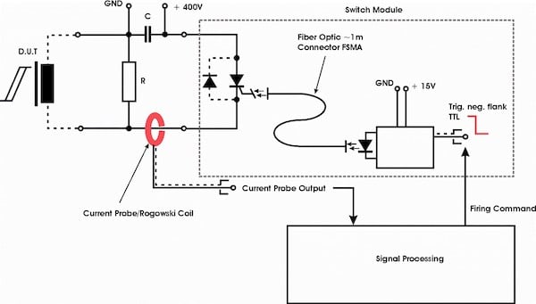
Figure 1. Basic Circuit Layout of the Pulse Generator (BsT-Pulse)
Capacitive discharge is a widely adopted technique for generating large current pulses. Charging a capacitor and accumulating stored energy are well managed in a controlled manner over a period larger than the discharge duration. The potential discharge energy is only limited by the capacitors used to store the charge and the voltage applied
The voltage pulse applied will drive the D.U.T. bipolar into saturation. Due to an integrated freewheeling diode, the resulting discharge circuit is capable of full current reversal. Hence, a saturation-desaturation-saturation transition will be created which can be monitored by current and voltage probes in order to determine the saturation properties respectively. Pulse energy is dissipated during the oscillation, in the form of voltage-current decay.
Option with JIG to Characterize Toroidal Shape Under Pulse
A mechanical fixture as JIG enables simple construction of DUT, consists of wires and core, the parasitic effects impacted for high-frequency oscillation can be kept as random, the mechanical construction of JIG is illustrated in Figure 2.
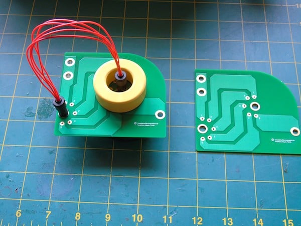
Figure 2. JIG, Core can be inserted/removed before/after measurement by plug the center pole
This set up enables the determination of magnetization behavior of any kind of soft magnetic material, especially for alloy powdered core with different composition, because the low permeable materials need large current amplitude to be illustrated for their soft saturation behavior, through voltage second calculation, with careful normalization with effective cross-section, the flux density can be traced, the whole measurement interval is limited in range of some µs and ms.
The consumption of metal alloyed powder materials is increasing double digital over the last 2 decades. A discussion takes place to integrate this kind of materials in IEC nomenclature, those metal alloyed powder materials usually exhibit permeability in a range between 26 and 200, it is very difficult to characterize the magnetic properties, especially the saturation behavior after the conventional way.
The Thyristor technology, capable of providing high kA amplitude under given applied voltage, usually under 250 Vpeak with full reversal current is definitely a potential candidate to meet this requirement.
Data Processing for Impulse Measurement
In general, the calculation of inductance through didt method has difficulty because of limited resolution of AD convert, and the transient measuring interval. The entire circuit consists of nonlinear D.U.T. for testing, limiting inductance (solenoid, a linear component) and a charging capacitor, Simulation can be performed by GeckoCircuit for analytical calculation of amplitude and differential inductance against the applied current amplitude, as shown in Figure 3.

Figure 3. Simulation Output Differential- (Green) and Amplitude (blue) Inductance.
The data processing of pulse measurement is a demanding task since the inductance is calculated as the quotient of the applied voltage and current incremental rate, which required a high sampling rate with high resolution for a diagram of inductance value in a reasonable manner. Due to its unique construction and simplified Thyristor technology the large-signal measurement can be performed with a moderate scope technique. The GeckoCircuit simulation result underlies this statement.
Further Potentials
BsT-Pulse can provide the inductance (amplitude, differential), (de) magnetization curve, and information about the non linear properties of magnetic components, additionally it enables calculation in terms of energy/power loss of the power choke with full reversal current amplitude, driving DUT back and forth to saturation, until the accumulated pulse energy disappears. That nonlinear characteristic can be illustrated with one single pulse, there are many different ways to consider and evaluate the loss of wire wound components, and it is definitely enrichment by introducing BsT-Pulse as an instrument to qualify wound components and its associated materials in use.
Discussion Part with Measuring Examples
Typical Power Choke with Iron Powder POT Core in Use
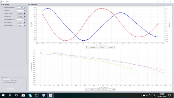
Figure 4. User Interface with integrated scope
With a single pulse, the power choke is driven back and forth into saturation, indicated by a distorted current wave, the voltage peak declines with dissipated pulse energy throughout power choke, the saturation behavior is clearly illustrated just within a single shot, the amplitude inductance can be expressed for a different odd cycle of oscillation. The different inductance vs. current relation is visible for different cycles, and this dependence is till now not specified yet, this is only possible with BsT-Pulse.
Short Circuit Measurement

Figure 5. Voltage and Current Decay of Measurement with Short Circuit
The most critical situation for BsT-pulse is the measuring condition with short circuit, with applied voltage till 1000 V, the capacitor and linear solenoid as limiting inductance builds up as LC resonance circuit, the damped oscillation process can be observed with its characteristics.
Comparison of measurement with iron base amorphous core (~23 kg), after annealing and after coating.


Figure 6. Voltage and Current Decay Comparison (Annealed and Coated), Pulsed @ ~ 100 V

Figure 7. Hysterese Loop, Out of the First Half Cycle, Comparison Between Annealed and Coated Status
Tape wound core made with iron-based amorphous material (~23 kg) is, it is clearly visible, the process (before and after vanishing process) has large impact of material properties, which are relevant for application design, and this difference can be quantified by bipolar impulse technology, the energy dissipation and power loss can be calculated respectively.
BsT-Pulse, based on Thyristor-Diode technology, is introduced to characterize the magnetic components and associated metal alloy powder material in use. The economic solution provides the largest current amplitude under high voltage, is attractive for installation industry, where more and more magnetic components have to be tested for mid voltage grid application, especially in developing countries, the full reversal amplitude opens further possibility to determine the loss behavior, and this important development gains increasingly importance for DC grid deployment
References
- Robin Nathan Comelius Pulsed Field Magnetometry for HighSpeed Characterization of Rare Earth Magnets
- Private communication with Teske
- Private communication with Müsing
- Private communication with Wang
About the Authors
JC Sun is the founder of Bs&T Frankfurt am Main GmbH, a company located in the north of the metropolis Frankfurt am Main and specializes in the development and manufacture of integrated hyster loop measuring systems. He worked for two decades as a development engineer in power electronics; developing various soft magnetic materials and was a project manager for various companies.
Andreas Müsing is one of the founders of Gecko-Simulations AG, a company developing tools as well as offering consulting services in the field of multi-domain numerical simulation and design of power electronic systems. He is a graduate from Eidgenössische Technische Hochschule Zürich in the field of Electrical Engineering, Power Electronics. He also took a course in the field of Physics at Ruprecht-Karls-Universität Heidelberg.
Christian Teske is the CEO of Consolidated Electrodynamics Limited, a private limited company located at London, England that offers engineering related scientific and technical consulting activities. He is also an independent researcher and had his Postdoc Position at the Institute of Applied Physics in Goethe-Universität Frankfurt am Main located in Frankfurt am Main, Germany.
This article originally appeared in the Bodo’s Power Systems magazine.