Dissecting the Proper Specification of Magnetic Components
This article highlights Bs&T Frankfurt am Main GmbH design of power magnetic components that requires proper specification for good reliability.
Design of power magnetic components for energy technique is a tedious task, mostly adopted with skilled craftmanship, among others there are two important criteria for a proper design, which are of thermic and magnetic nature.
Those two criteria interact with each other, which makes academic articulation difficult, winding activity is mostly impressed by engineering and experience, it becomes more challenging for the ever-increasing requirement of high efficiency and high-power density, for proper specification and verification, especially for magnetic component with the rated current higher than 22A. Since there is no micromagnetic model existing, enabling analytic approach to address the nonlinearity of magnetic components, measuring is indispensable, and impulse technique, with its transient high current amplitude to characterize saturation behavior, and eliminates the thermal effect during the measuring period, is widely accepted by power magnetic component manufacturer.
Nowadays for the measurement of inductance, a bipolar thyristor (SCR silicon-controlled rectifier) can be used to start a damped oscillation. The full reversal current enables loss measurement.
Principle of Thyristor-based Damped Oscillation Impulse Technology
The control current for the thyristor is generated by fiber-optic signal processing. This activates a serial resonance circuit consisting of the main discharge capacitor, a safety inductance, and the inductive test object. Hence, the main discharge capacitor is discharged and, depending on the charging voltage, a high current pulse is generated that is suitable to provide the test object with the current. Both the maximum peak amplitude of the discharge current as well as the current rise rate can be limited by appropriate sizing of the safety inductance.
The two analog inputs of the digital oscilloscope record via suitable probes or current measuring devices the current-voltage curve of the test object in order to extract the current behavior of the test object. Since in most cases the resulting resonance circuit is subcritical damped, a freewheeling diode allows the current reversal and thus a bipolar control of the test object, which is advantageous for numerous applications, such as measuring the saturation behavior of inductors.
Differential Permeability and Inductance
If a current flows through a straight coil that is very long in relation to its cross-section, a homogeneous magnetic field H = NI / l is created in the coil via the cross-section. This generates a magnetic induction or flux density B = μ0 · H.
H — the magnetic field strength in A/m
N — number of turns of the coil
I — the current strength in A
l — length of the coil in m
B — flux density in Vs/m²
µ0 — magnetic field constant 4π · 10-7 Vs/Am
If a magnetizable material exists inside the coil and is this demagnetized or in the magnetically neutral state before switching on the current, the rise of the flux density happens along the initial curve. This has the same course as the commutation curve, which arises when symmetrical hysteresis loops are controlled at different levels and their endpoints (µa) are drawn as a B-H curve. Inside the material, a flux density B = μ0 · μr · H is generated. If the current is further increased, the material can achieve the magnetic saturation. This is characterized by µt = 1 (Figure 1, point E). µt is the total permeability.

Figure 1: B-H Loop, 1. Quadrant
Different permeabilities can be defined on the initial curve and the hysteresis loop.
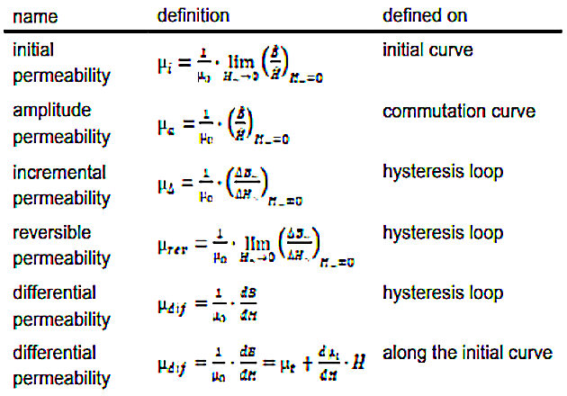
If the field strength for the incremental permeability is made to zero, one obtains the differential permeability µdif. The slope of the hysteresis loop or the initial curve is defined by μdif · μ0 for any pair of values (B, H) on that curve.
$$\mu _{dif} = \frac{1}{\mu _0} \cdot \frac{d \beta}{dH} = \frac{1}{\mu _0} \frac{d(\mu _0 \mu _tH)}{dH} = \frac{1}{\mu _0} \frac{\mu _0 d(\mu _tH}{dH} ... $$
$$...=\frac{d(\mu _{t}H)}{dH} = \mu _{t} \cdot \frac{dH}{dH} + H\cdot \frac{\mu_{t}}{dH}= \mu _{t}+\frac{d_{A1}}{dH}\cdot H$$
Looking at the initial curve, and particularly in the region of small excitation, the so-called Rayleigh region, µt = µi = µdif at H=B=0. Between H=0 and the inflection point of the initial curve, the differential permeability rises faster than the total permeability. At the inflection point of the new curve, the derivation of dµt / dH is zero and then it drops steeply. At the point µt = µtmax the value of µdif is also equal to µtmax (Figure 1, point H) and for further increasing the H field µdif drops fast towards 1 (Figure 1, point E).
When the current direction is reversed and thus the field strength direction, the flux density does not decrease again along the initial curve, but on the upper branch of the hysteresis loop. The differential permeability rises only slowly and faster when approaching + Br (Figure 2, point F). At – HC (Figure 2, point G) µdif reaches a maximum because the hysteresis loop has an inflection point here. After that, it drops steeply and becomes 1 again when the negative saturation is reached (Figure 2, point A).

Figure 2: B-H Loop full range
After the reversal of the current and thus the magnetic field in a positive direction, the lower branch of the hysteresis loop is passed from A to E in the same way as before from E to A. The differential permeability has a maximum at + HC now.
Replacing the flux Φ = B · A by the linked flux N · Φ = ψ = N · B · A and the magnetic field strength H = Ni / l by i = Hl /N and if these are applied in the diagram instead of B and H, the following hysteresis loop is obtained with Ψ = f(i).

Figure 3: Ψ - i course
The increase in the function Ψ = f(i) is the inductance instead of μ0 · μ for B=f(H). Similarly, the differential permeability becomes the differential inductance Ldif.
Lb(i) = ΔΨ / Δi = ∫υdt / Δi and L(i)dif = dΨ /dt / dt/dt = dΨ /dt
If hysteresis losses are neglected, Ldif corresponds to the reversible permeability Lrev of the magnetizable material and can be used to determine the amplitude of a current ripple biased with direct current.
The amplitude inductance defined on the initial curve or the commutation curve at a peak current Ipeak can be specified as follows.
La = Ψpeak / Ipeak.
In the same way, the inductance L, let’s call branch inductance Lb can be defined as Lb = ΔΨ / Δi on any branch of the hysteresis loop.
By means of this, the maximum permissible flux density of an application can be determined.
At Ipeak, Ldif should have dropped maximum to the half of its maximum.
With the BsT-Pulse measuring device, both the branch inductance Lb(i), as well as the differential inductance L(i)dif, can be measured under thyristor-based damped oscillation excitation. As well as the energy equivalent inductance [4] can be validated with data processing. This measurement is possible for the magnetization branch from B to E in Figure 3 as well as for the demagnetization branch from E to F. The exact functioning of Bs&T -Pulse is described in [1].
Application example with gapped ferrite design:
Gapped Ferrite design is widely adopted for industrial application, the sheared hysteresis loop, with decreased the remanence, enlarge the linear working area, the postulation is correct according to reluctance model, different ways to manage the same total air gap length has well consequence in terms of inductance course and thermal dissipation. This can be measured with BsT-pulse damped oscillation technology.
The largest ETD shaped core is taken, and large air gap length is taken to design storage choke.

Figure 4: ETD 59 with a total air gap length of 3,0 mm in the center leg
For measurement with the BsT-Pulse, the capacitor of the device is charged to a voltage corresponding to the application, here in the example 300V. The capacitor, the measuring object, here an ETD 59 with 3.0 mm central air gap with a coil with 17 turns and a safety inductance form a series resonant circuit. When the capacitor is discharged, a damped oscillation is formed as seen in Figure 5.

Figure 5: Voltage and current course of damped oscillation
For the evaluation of the branch inductance and the differential inductance, the first positive half-wave of the current, as shown in Figure 6, is used.

Figure 6: first positive half-wave excitation
The evaluation is carried out in two sections.
Section 1: Magnetization of the measuring object from I = 0 A to I = Imax, left of the dashed line in fig. 6. This corresponds to the hysteresis loop in figure 3 either the lower branch of the loop or the initial curve, depending on the state in which the measuring object was before the measurement.
Section 2: Demagnetization of the measuring object from I = Imax to I = 0 A, right of the dashed line in figure 6. This is done along the upper branch of the loop in Figure 3.
Lb (i) increases with the increase of the current until the permeability µ has reached its maximum and then becomes smaller again to the saturation. Here, only the inductance of the empty coil is measured. When reaching the maximum current at approx. 480A, the current direction reverses and the measuring object is demagnetized along the upper branch of the hysteresis loop.

Figure 7: Lb = f(i) Magnetization

Figure 8: Lb = f(i) Demagnetization
Figure 9 shows the course of differential inductance during magnetization. The maximum of Lb and Ldif has the same value, but Ldif reaches the maximum slightly earlier than the inductance Lb. After that, Ldif drops steeply, while Lb goes slowly into saturation. While demagnetization (fig. 10) along the upper branch of the loop, Ldif stays very small for a long time until near HC and then rises steeply but falls again when the current approaches towards zero.
The proper specification and verification of magnetic components with gapped ferrite are provided with complete inductance analysis at operation temperature, same impulse testing can be accompanied with extended operating temperature range to illustrate the nonlinearity of inductor, decoupled with self-heating disturbance is presented.

Figure 9: Ldif = f(i) Magnetization

Figure 10: Ldif = f(i) Demagnetization
Magnetic component with rated current higher than 22 A is nowadays not properly specified, the technological implication and associated with measurement difficulty is well described in IEC 62024, the high power and high current power electronics application, especially for high power wireless charging, filter for mid voltage DC grid and automotive application, requires proper specification, in good sake of reliability. BsT-pulse, thyristor-based damped oscillation technology, enables proper specification and validation of bulky reactor. Easy operation and transparent data processing can be implemented for online diagnosis and online monitoring.
About the Authors
JC Sun is the founder of Bs&T Frankfurt am Main GmbH, a company located in the north of the metropolis Frankfurt am Main and specializes in the development and manufacture of integrated hyster loop measuring systems. He worked for two decades as a development engineer in power electronics; developing various soft magnetic materials and was a project manager for various companies.
K. Seitenbecher worked for Bs&T Frankfurt am Main GmbH, a company located in the north of the metropolis Frankfurt am Main and specializes in the development and manufacture of integrated hyster loop measuring systems. He worked for two decades as a development engineer in power electronics; developing various soft magnetic materials and was a project manager for various companies.
Literature
- Pulsed Field Magnetometry for Characterization of Magnetic Component; Bodo´s Power Systems, March 2019
- Ferritkerne; Kampczyk_Röß
- Soft Ferrites; Snelling
- Inductors and Transformers for Power Electronics Vencislav Cekov Valchev, Alex Van den Bossche
This article originally appeared in the Bodo’s Power Systems magazine.