How to Hot Plug Sequence Your BMS Cell Connections
This article discusses hotplug sequencing and how to implement the cell connection sequences.
Lithium-ion (Li-ion) batteries are used in a wide variety of portable system applications, including vacuum cleaners, lawn equipment, handheld power tools, e-bikes, and energy storage systems. Li-ion batteries are smaller, weigh less, and deliver longer battery life than other battery chemistries, but require monitoring and protection for safe use.
The main task of a battery management system (BMS) is to protect the battery pack, and the key BMS device to aid with protection is the battery pack monitor. It monitors the voltage of each pack cell, as well as overall battery pack voltage, temperature, and current. Monitoring these parameters allows the BMS controller to maintain a safe window of operation for the pack and its individual cells.
While there are many aspects to BMS device operation, this article discusses hot plug sequencing and how to implement the cell connection sequences. These sequences characterize a BMS device’s hot plug performance. Most engineers are familiar with the term hot plug. However, when dealing with BMS devices and developing hot plug test permutations, engineers need to keep efficacy in mind due to the many BMS connections. A single battery pack monitor can have up to 15 or more hot plug connections.

Figure 1. A hot plug test requires programmable switching for control/ timing of each cell connection
Hot Plug Test Operating Conditions
Testing for BMS device hot plug robustness requires several “live” cell connections as shown in Figure 1. Because battery cells do not have an off switch, your connections will have active source/sink voltages. And given that you’ll have multiple wired BMS-to-pack inter-cell connections, the BMS device must have extremely robust hot plug performance. It must be able to handle any order of connections made in production or the application environment. The BMS’ controller is exposed to hot plug conditions each time you attach a new pack. One of the main problems during hot plug is that the BMS device’s various circuit blocks are receiving power before the main rails are established, which can make the circuits behave in unexpected ways. A battery pack monitor, like the ISL94203 or ISL94202, can address this issue by controlling the impedance of critical circuit nodes during the hot plug event.
Hot Plug Test Coverage Goals
Many device aberrations can occur during the hot plug process, so it’s important to achieve these fault detection goals during the hot plug test process.
Corrupt POR — Improper State-Machine Start-up
This problem centers on the BMS control device starting before the completion of all connections. While this may not be catastrophic, it can result in ATE failures during the production process. Early POR can result in startup failures. Therefore, new hot plug test methods include detection of early POR or device activation during the pack connection process.
Internal Logic Malfunction — Abnormal Digital Status
This occurs when digital logic levels have metastable conditions. Metastable is where logic levels are between valid voltage threshold levels. The result is digital status registers reporting abnormal bit combinations. Hence, the test apparatus must include device communications (I2C, SPI) during hot plug testing, as shown in Table 1. Abnormal digital status can lead to ATE failures requiring a device restart.
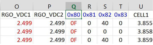
Table 1. Hot plug testing records the BMS device’s internal registers via I2C or SPI communications bus
Analog Bias Malfunctions — Inaccurate Voltage Readings
This is a condition where internal analog reference or bias levels do not reach proper levels. Abnormal bias may lead to permanent offset in internal and measured analog values. These offsets can result in permanent error conditions that require a complete power re-cycle to clear. Figure 2 shows the analog multiplexer (MUX) measurement data after the completion of a hot plug sequence.
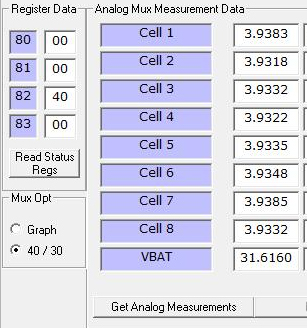
Figure 2. Analog voltage measurements enable change detection in MUX performance
Formulating Hot Plug Connection Sequences
BMS hot plug robustness needs to address random power sequences. These sequences define the order of connection from cell measurement nodes to active cell voltages. The definition of these sequences can become a study all to itself. Previous efforts at hot plug testing suggested the need for many thousands of connection sequences. Figure 3 illustrates the switched connection sequences for a hot plug test. In developing new connection sequences, we offer a few different approaches that are the result of many years of test development.
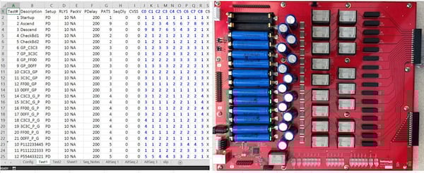
Figure 3. Hot plug tests consist of switched connection sequences
Connection Sequences Based on Memory Test Pattern Efficacy
In addition to defining your hot plug connection sequences, you’ll also want to include a memory testing (pattern generation) approach. In fact, memory testing is the dynamic performance testing of the memory bank’s power distribution. And, certain types of test patterns stress power distribution more than others do.
For example, a recent industrial BMS hot plug test project required the switching of nine connections made in a random fashion. The connections included VSS (pack-), VBAT (pack+) and 7-cell monitor connections. Therefore, from a memory test pattern viewpoint, there are nine bits.
Other BMS devices have up to 15 or more connections. If connection sequence design comes from a mathematical permutation viewpoint, then thousands to millions of tests are necessary. Note that each test requires the time to power down from the last test, execute the connection sequence and then confirm POR status. After completion of the hot plug sequence, each test triggers a POR cycle. The test then checks digital status registers and finally records analog measurement of all pertinent MUX channels.

Figure 4. View of BMS hot plug connections from an overall circuit stress viewpoint
To support the memory viewpoint, let’s review memory test patterns and their targeted fault detection. Here is a list of memory fault conditions:
- SAF = Stuck-At Fault
- TF = Transition Fault
- CF = Coupling Fault
- NPSF = Neighborhood Pattern Sensitive Fault
- AF = Address Decoding Fault
Reviewing these fault models, and transitioning from memory circuits to hot plug testing, some faults actually target hot plug failure mechanisms. The observation is that faults 2, 3 and 4 are pertinent to hot plug fault detection. Certainly, as different hot plug connection patterns occur, transition faults, coupling faults and neighborhood pattern sensitives are possible. Coupling and neighborhood fault detection is especially suitable for the hot plug test effectiveness.
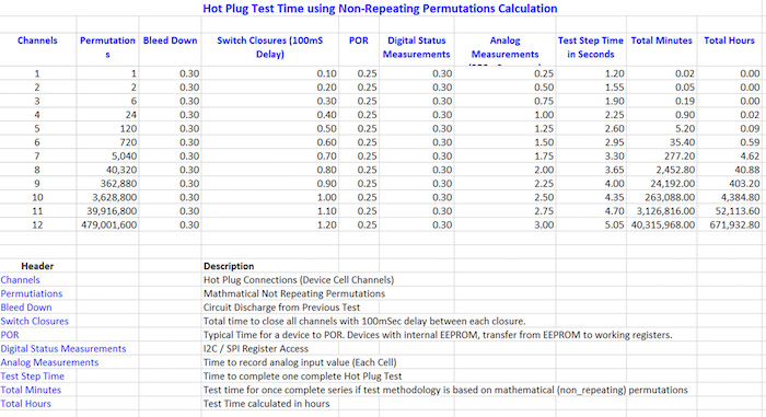
Table 2. Connection sequences using calculated, non-repeating permutations is not practical in a real-world lab environment
Therefore, newly designed hot plug sequences apply stress to the internal biasing of the connections. This stresses device conditions to a greater degree than the simple one at a time approach. Combinational patterns such as checkerboard add to walking 1s, and walking 0s are basic patterns used during this version of hot plug testing. As shown in Figure 4, a BMS device needs to control the impedance of the input switches during hot plug events so that the IC’s input signals are also controlled.
Connection Sequences Based on Single Cell, One at a Time
These patterns have basic concepts about one at a time connection patterns. Examples are simple ascending and descending closures, and there is semi-random, one at a time sequences. The goal here is to use efficient pattern selection but limiting the quantity of these types of sequences. This keeps test runs within a reasonable length of time.
Strictly applying non-repeating permutation calculations can result in impractical hot plug testing logistics. Table 2 reveals estimated nine connection hot plug test times of more than 400 hours. This approach is not practical for device repeat testing, multiple device testing or timing variation.
Connection Sequences Based on Hardware Interconnect Design
A final consideration is the mechanical aspects of connectors. Hardware interconnect design addresses the number of connections made with each connector, and considers the overall organization of electrical distribution. Designs can use 2-, 3- and 4-cell connections with a single connector, which means that a connected battery pack involves a collection of connectors.
Also the interconnect design can include cell monitor connections made separately from the main pack- and pack+ nodes. Other designs might parallel pack- and pack+. The result is the main supply points are physically attached to two different connection points. In short, sequences based on hardware interconnects are driven by the schematic.
Connection Sequences with Interconnection Delay
Connection sequence design includes a programmable delay. Each test step, in addition to specifying the closure sequence, also includes a variable as part of the test definition. This variable is a programmable delay between closures. Therefore, in the interest of test time, early testing keeps the delay short. Follow on test runs can then increase the delay value to emulate the real-world time it takes between battery connections.
It’s always better not to base sequences on mathematical permutations alone. Rather, sequences should be a combination of three types. The first type of sequence is the selection of one at a time patterns. The second type is several at a time based on effective input stressing. And the third is basing sequencing combinations on connector schemes, i.e. physical contacts per plug assembly.
With a focus on sequence efficacy, reiteration of test runs is possible. This enables the testing of multiple devices. Sequence efficacy reduces test time so personnel can be on-hand from a safety standpoint. Finally, the timing of the test processes can expand to emulate delays naturally occurring in the factory/user connection process.
Hot Plug Performance is Key
Hot plug performance is key to device qualifications when you are designing battery management systems. In this article, we have reviewed many aspects of BMS hot plug testing and sequence design. We’ve also listed the desired failure coverage that should be followed. Along the way, we learned that focusing on connection sequencing (and timing) addresses an issue that fundamentally drives the essentials of practical hot plug testing. Engineers should consider sequence development as a continuous process. Future development will primarily be driven by the BMS-to-pack interconnect. Test conditions also rely on reference designs and their variations.
About the Author
Robert Grist holds a Radiotelephone Operator License and has undergone training in Basic Fortran at Hewlett Packard Skokie, IL Software Training Center. He has also undergone Computer Programming, Assembly Language, and Cobol at Johnson County Community College. Currently, He works at Intersil, a Renesas company as a Senior Software Developer / Applications Engineer.
This article originally appeared in the Bodo’s Power Systems magazine.