High-Precision, Wideband, Highly Stable Current Sensing Technology
This article introduced the detection principle used by the zero-flux method, key considerations when choosing a current sensor and some precautions.
Currently, there is demand for high-precision, wideband current measurement in the power electronics field, where typical products include power conversion systems such as power conditioners and inverters. Since launching the Clamp Tester CT-300 (see Figure 1) in 1971, Hioki has supplied a variety of current sensors (see Figure 2) designed for specific measurement applications. This paper describes the features of Hioki’s current sensors along with key considerations in current measurement, with a focus on high-precision, wideband current measurement.
Detection Methods Used in Current Sensors
Current sensors utilize a broad range of detection methods. Among them, many detect current using a magnetic conversion element that is inserted into the gap of the magnetic core or a winding making up a magnetic core, depending on the current flowing in the conductor under test. That said, each detection method is characterized by its own advantages and disadvantages, making it difficult to satisfy all measurement requirements with any one detection method. Hioki provides high-precision, wideband current sensors by using the zero-flux method (also known as the closed-loop or magnetic balance method), which combines two detection techniques.
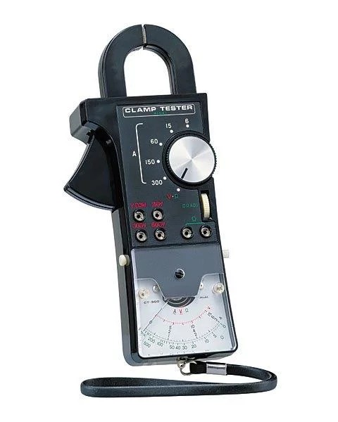
Figure 1: Clamp Tester CT-300

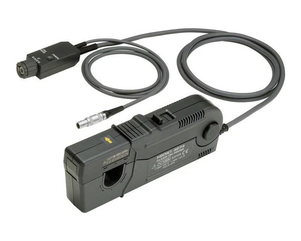


Figure 2: Variety of current sensors
In the zero-flux method, which relies on a negative feedback circuit that includes a magnetic circuit such as those shown in Figures 3 and 4, a current is made to flow in a feedback coil so as to cancel the magnetic flux produced in the core by the current under measurement. This method has the advantage of minimizing the effects of the magnetic material’s nonlinearity since the operating magnetic flux can be controlled so that it is kept to a very low level.
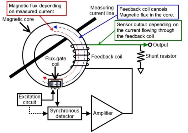
Figure 3: Flux-gate method and the current transformer (CT) method
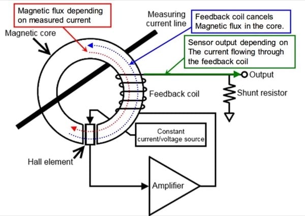
Figure 4: Hall element and the current transformer (CT) method
Hioki’s high-precision current sensors use the zero-flux method, which combines the flux-gate method and the current transformer (CT) method shown in Figure 3. The flux-gate method allows detection based on a DC current. Because this method does not require use of any semiconductors, it delivers the advantages of low offset voltage, high temperature stability, and excellent long-term stability. Hioki provides current sensors with 0.02% rdg. accuracy and a band of 3.5 MHz, making them some of the best-performing instruments of their kind in the world. In addition, the company takes advantage of the flux-gate method’s high temperature stability to deliver products with an operating temperature range of -40°C to 85°C.
By contrast, wideband current sensors use a zero-flux design that combines a Hall element and the current transformer (CT) method as illustrated in Figure 4, providing a measurement band that extends from DC to a maximum of 120 MHz. Since Hioki produces in-house the Hall elements that serve as the key magnetic detection devices in this design with high sensitivity and low noise characteristics, these sensors are ideally suited to use in applications where minuscule current waveforms must be observed in combination with an oscilloscope.
Differences in Current Sensor Architectures
Current sensors can be categorized as either through-type or clamp-type instruments based on their design. The through-type architecture eliminates any break in the surface of the magnetic core, which makes it easy to obtain uniform characteristics around the entire circumference of the core and allows construction of extremely high-precision current sensors. However, this design requires that the wire under test be disconnected so that it can be passed through the sensor, making it impossible to connect the sensor to operating equipment.
By contrast, the clamp-type architecture introduces a break into the magnetic core, allowing it to be clamped around the wire being measured. Since there is no need to disconnect the wire under test as with the through-type design, it is easy to measure operating equipment. However, the introduction of a break into the magnetic core makes it difficult to obtain uniform characteristics around the entire circumference of the core. As a result, clamp-type current sensors generally exhibit lower measurement accuracy and have a more pronounced effect of conductor position than their through-type counterparts. Consequently, they make it more difficult to obtain measurements with good reproducibility. Hioki takes advantage of expertise gained over many years of developing current sensors to offer high-precision, clamp-type current sensors. The characteristics of these instruments are described below.
Key Considerations When Choosing a Current Sensor
The most important aspect of making high-precision measurements with a current sensor is the selection of a current sensor that is appropriate for the measurement target.
Many high-precision current sensors (i.e., those with an accuracy of 0.1% or less) uses the current output method, but Hioki’s high-precision current sensors uses the voltage output method. While current output is generally regarded as providing superior signal transmission quality, voltage output delivers numerous advantages as an output format for current sensors. The following sections describe key considerations when choosing a current sensor while exploring the advantages of voltage output.
Suitability of the Current Sensor’s Rating and Measurement Band
To measure a given current with a high degree of precision requires a current sensor whose rating is appropriate for the magnitude of the target current. For example, if a 5 A current were measured using two current sensors with the same accuracy specifications, one with a 10 A rating and one with a 500 A rating, the results would indicate that the sensor with the 10 A rating, which is closer to the magnitude of the measurement target, is advantageous in terms of precision and reproducibility. Caution is necessary as Hioki defines rated currents for its current sensors as RMS values, whereas many current sensors do so using peak values.
In addition, it is important to verify that all frequency components of the current to be measured are included in the current sensor’s measurement band.
Defined Accuracy for Amplitude and Phase in the Measurement Band
For most high-precision current sensors used in combination with power meters, amplitude accuracy is defined only for DC current and commercial frequencies (50 Hz/60 Hz), and phase accuracy is rarely defined at all. In fact, it is difficult to define the accuracy of amplitude and phase in the high-frequency region for the current output that is generally used by high-precision current sensors. Caution is necessary as many manufacturers only publish typical characteristic graphs for frequencies other than commercial frequencies. Since Hioki sensors use voltage output, it is possible to define amplitude and phase accuracy across the entire measurement band. Because both amplitude accuracy and phase accuracy are critical considerations in accurate power measurement, it is important to verify that phase accuracy has been defined when choosing a current sensor, particularly one that is to be used in power measurement.
Versatility
Current sensors that produce voltage output have the advantage of being suitable for a variety of measurement applications since it is easy to connect them not only to power meters, but also to instruments such as DMMs, oscilloscopes, and recorders.
High S/N ratio
Hioki’s high-precision current sensors are designed to produce 2 V of output when measuring the rated current. For example, when using the Hioki CT6863 (rated 200 A), 2 V AC would be input to the power meter when measuring a 200 A AC. Since power meters that accept current input incorporate shunt resistors into their input circuitry, even signals from current sensors that produce current output end up being converted to voltage signals for processing. If a high-precision current sensor with a conversion ratio of 1500:1 is used to measure a 200 A AC current, the voltage measured by the power meter will be as follows for the typical shunt resistor resistance values of 0.5 Ω and 0.1 Ω:
133.3 mA × 0.5 Ω = 66.65 mV AC
133.3 mA × 0.1 Ω = 13.33 mV AC
The signal levels measured by the power meter would be 2 V (with Hioki’s design) versus 13.33 mV to 66.65 mV (for a current output-type design), illustrating how the Hioki design yields a higher S/N ratio than current sensors that rely on current output.
Ease of Adjustment and Calibration
Since Hioki’s current sensors generate voltage output, they have the advantage of being easy to adjust and calibrate. Consequently, their defined accuracy can extend to include the output cable. In addition, Hioki sensors can be manufactured with custom cable lengths since the adjustment process can compensate for the minuscule voltage drop caused by the cable’s resistance.
Hioki’s high-precision current sensors can be calibrated not only for DC and commercial frequencies, but also for the high-frequency region. Following are some example calibration points for Hioki’s current sensors (traceability is maintained for each frequency point):
Amplitude: ±DC, 50 Hz, 60 Hz, 1 kHz, 10 kHz, 100 kHz, 300 kHz, 700 kHz, 1 MHz
Phase: 50 Hz, 60 Hz, 1 kHz, 10 kHz, 100 kHz, 300 kHz, 700 kHz, 1 MHz
Precautions for High Precision Measurement
This section introduces some precautions that should be observed when using a current sensor to measure current with a high degree of precision, based on the experience Hioki has gained over many years of current sensor development.
Positioning the Conductor in the Center of the Sensor
All current sensors are prone to the effects of conductor position, and the magnitude of those effects increases with the measurement frequency. Even through-type current sensors with good characteristics exhibit significant effects at frequencies of 10 kHz and above. A current sensor’s measurement accuracy is always defined at the center position of the sensor. When measuring a high-frequency current, it is particularly important to ensure high-precision, highly reproducible measurement by positioning the conductor in the center of the sensor.
Keeping Nearby Conductors away from the Current Sensor
Current sensors function by detecting the magnetic field produced when current flows through the cable being measured. As a result, they are affected in no small part by any currents that may be flowing in nearby conductors. These effects are particularly pronounced for high-frequency currents. Consequently, it is desirable to keep nearby conductors as far away as possible from the current sensor so that the target current can be measured at a high level of precision. These effects are particularly significant for high-frequency currents, and they should be considered when using all current sensors.
Expressing the Accuracy of High-Precision Current Sensors
The accuracy of Hioki’s high-precision current sensors is defined for all frequency bands in the measurement domain. Current sensor accuracy is typically defined in the center of the sensor. However, it is no easy feat to position a conductor in the exact center of the sensor in actual practice. Figure 5 illustrates the frequency characteristics and specifications of a Hioki high-precision current sensor (Model CT6841). Accuracy has been defined for each region so that the specifications are satisfied even when the conductor position varies.
In addition, the accuracy specifications of Hioki’s high-precision current sensors incorporate a sufficient margin of performance. As a result, actual performance tends to be significantly better than their specifications suggest.
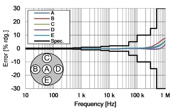
Figure 5: Frequency characteristics and specifications of a Hioki high-precision current sensor
High-Precision Current Clamp Sensors
As described above, clamp-type current sensors generally exhibit poor accuracy and measurement reproducibility due to the break in their magnetic core. This section introduces some of the characteristics of Hioki’s CT6843 high-precision clamp sensor (rated 200 A), shown in Figure 6. Figures 7 through 9 compare those characteristics to those of the CT6863, a Hioki through-type current sensor with the same rating (200 A). The characteristics of Hioki’s clamp-type current sensors approach those of through-type current sensors, making them more than capable enough to be used in high-precision power measurement.
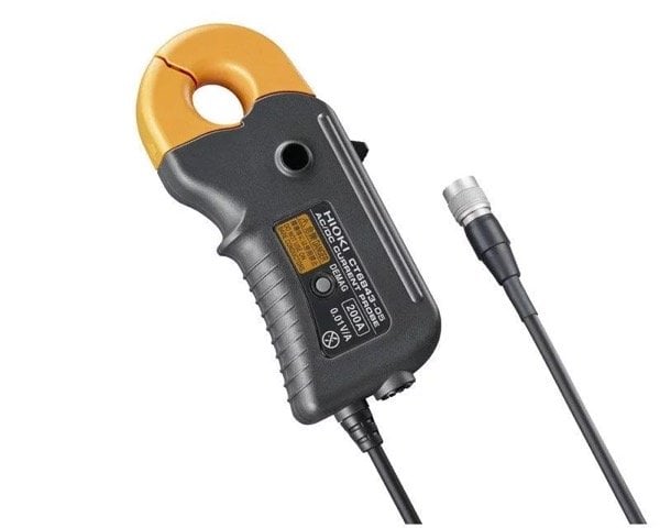
Figure 6: Characteristics of Hioki’s CT6843 high-precision clamp sensor (rated 200 A)

Figure 7: Comparison to the characteristics of the CT6863 Hioki through-type current sensor
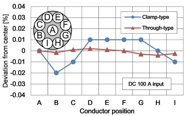
Figure 8: Comparison to the characteristics of the CT6863 Hioki through-type current sensor
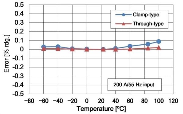
Figure 9: Comparison to the characteristics of the CT6863 Hioki through-type current sensor
These clamp-type current sensors are able to deliver this level of performance because they use a uniform structure around the circumference of the magnetic core with the exception of the break and because the break in the core is designed to minimize magnetic reluctance. This construction evokes designs that deliver uniform characteristics around the entire circumference of the magnetic core as in a through-type sensor.
Hioki’s clamp-type current sensors are designed to deliver excellent ease of use as well as high performance. For example, their jaws can be opened and closed, and their sensor locked in place, by means of simple, single-handed operation. Furthermore, these sensors can operate across a broad temperature range of -40°C to 85°C, allowing their use in a variety of environmental tests. As a result, they can be used without issue in harsh environments such as the hot conditions of an automobile’s engine compartment.
In addition, Hioki’s power meters are designed specifically to be used with its current sensors, allowing them to supply power directly to, and automatically detect the model of, connected sensors. For this reason, Hioki’s current sensors are ideal for use in conjunction with power meters in high-precision, wideband power measurement applications.
Wideband Clamp-Type Current Sensors
Hioki’s wideband current sensors feature a broader measurement band and lower noise levels than the high-precision current sensors described above. Of those products, the CT6701 (Figure 10), which has the highest current to output voltage conversion rate (“output rate”) and highest frequency band (see Figure 11) of any Hioki product in its class, is ideal for use in the observation of transient response current waveforms, high-speed response waveforms such as inrush current, and minuscule current waveforms that include a variety of frequency components.

Figure 10: CT6701 has the highest current to output voltage conversion rate
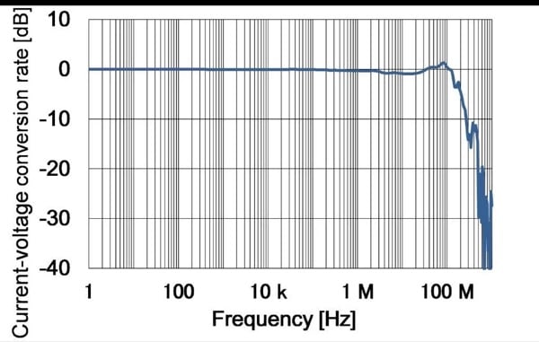
Figure 11: CT6701 has the highest frequency band
As described above, wideband current sensors use the zero-flux method, which utilizes a thin-film Hall element. Hioki has developed a thin-film low-noise Hall element, which is a key device in current sensors, to accommodate market demand for improved low-current measurement capabilities. For example, the Hioki CT6701 is able to deliver an output rate of 1 V/A (10 times the rate of its predecessor) as well as low-noise performance. Figure 12 provides a measured waveform comparison with the previous model, illustrating how the waveform of a control current flowing to an electrical part in an automobile, for example a small motor, can be more precisely observed on the order of milliamperes. Using them in combination with an oscilloscope is ideal for fully optimizing the performance of the 120 MHz (-3dB) wideband characteristics. For example, it can be used to observe the control current or load current in a switching circuit used in power conversion or motor control, the turn-on/turn-off current waveform of a semiconductor device performing high-speed switching, or ripple waveforms.
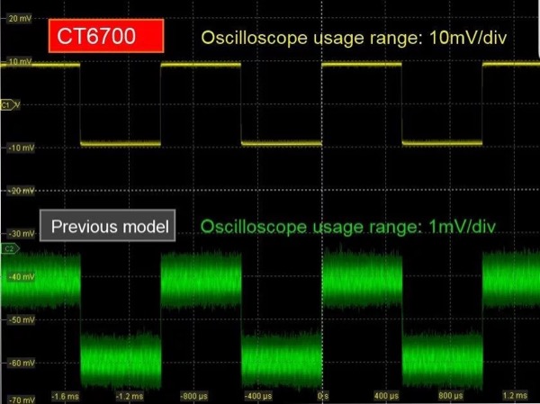
Figure 12: Measured waveform comparison with the previous model
Conclusion
This article has introduced the detection principle used by the zero-flux method, key considerations when choosing a current sensor, precautions when using these instruments, and some current sensor characteristics, with a focus on current sensors that have been developed by Hioki for more than 40 years. The authors hope that it will prove useful to anyone measuring current in the power electronics field, which demands high-precision, wideband current measurement.
About the Authors
Kenta Ikeda,and Hidekazu Masuda both work as Senior Staff at Hioki E.E. Corporation, a company established in 1935, HIOKI E.E. CORPORATION has grown to become a world leader in providing consistent delivery of test and measuring instruments through advanced design, manufacturing, and sales and services. By offering over 200 main products characterized by safety and quality while meeting an expansive range of applications, we aim to contribute to the efficiency and value of our customers’ work in research and development, production and electrical maintenance.
This article originally appeared in the Bodo’s Power Systems magazine.