Busbar Handles More Power without Adding More Size
This article discusses a method of increasing power of busbars without adding size by combining Power Ring Film Capacitors with busbars assemblies.
Electronic power distribution has long been a function of laminated busbars. They typically provide a compact design improving system reliability and have low inductance and impedance. As requirements for power distribution in electric vehicles, from solar inverters and from wind turbine inverters, grow more complex, developers of laminated busbars are challenged to handle higher power levels with greater power density—in effect, to make smaller and lighter busbars that can channel higher power levels than ever before. More power usually implies wider conductors and larger busbars.
Nowadays the requirements for high power density and increased reliability are not only important for busbars but also for complete inverter design. That’s why a combination of special Power Ring Film Capacitors™ and busbar assemblies offers a new solution for demanding applications. Compared to current available solutions, the combination reduces total system costs, improves reliability and increases power density.
Electronic systems rely on efficient combining and distribution of voltages from different sources. In higher-power applications such as solar and wind inverters and the powertrains of electric vehicles (EVs) and hybrid electric vehicles (HEVs), energy must be channelled with minimal combining and distribution loss. An ongoing challenge for these inverter systems is to develop power distribution components such as laminated busbars that are rugged enough to handle high power levels without simply making them larger than existing laminated busbar designs.
A solution lies in a different approach to busbar design, using an assembly configuration of laminated busbar from Rogers Corporation and Power Ring Film Capacitors™ from SBE, Inc. The resulting solution is a metallized polypropylene film capacitor in a low-profile, ring-shaped form. It adds minimal volume and weight to the busbar capacitor assembly while dramatically increasing power density. With this approach, it has been possible to reduce significant equivalent series inductance (ESL) and keep the compact design due to a high aspect ratio form factor and increased power density.
Keeping Busbars Small in Size but Powerful Enough
Busbars are indispensable circuits for routing power to many circuit branches and components within an electronic design. As an example, they are visible on solar panels as the circuit lines running from one photovoltaic (PV) cell to another, with the voltages added in series to achieve the final output voltage of a solar panel. They are not as visible but just as essential for power distribution with solar- or wind-based power-generating systems. They must be compact to fit within the circuitry of equipment enclosures, and have low inductance and loss to minimize performance degradation or even breakdowns from power surges and potential overheating caused by ripple currents.
Busbars are essential components in energy storage and distribution systems, including for connections of solar panels and wind turbine inverters to the electric grid. As solar and wind inverters for home and industrial applications continue to achieve higher power levels, busbars are required to channel higher voltages and currents but without adding size to previous busbar solutions. The problem lies in developing physically small busbars capable of handling the higher power presented by solar and wind inverters as well as the power distribution systems in EVs and HEVs.
Handling Power Surges
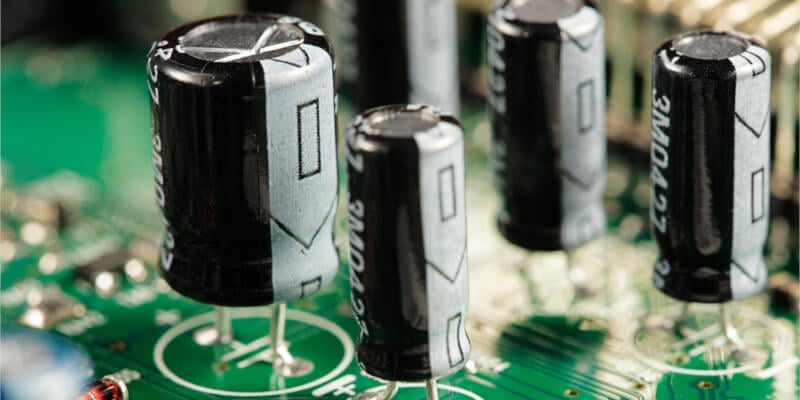
The high power density and capability to survive power surges caused by ripple currents for high-voltage power-switching applications usually requires banks of large-value electrolytic capacitors along with high-frequency bypass capacitors to handle cases of ripple currents. Adding such components to a busbar typically increases size and weight. But because of the low profile of the annular Power Ring Film Capacitor, very little size and weight is added to the ROLINX busbar, although voltage and current carrying capacities are dramatically increased. The film capacitor features inherently low equivalent series inductance (ESL) and equivalent series resistance (ESR) to handle high power levels while minimizing the thermal degradation and heating effects suffered by circuits with higher losses.

Figure 1: This novel busbar assembly combines a laminated busbar with a low-profile, annular capacitor for improved power-handling capability in a compact form factor.
Attaching the Capacitor
An important step in making this busbar/ capacitor combination practical is the method of attaching the capacitor to the busbar. The combination of materials in each component exhibits a complex coefficient of thermal expansion (CTE) not only between each layer of material in the busbar and the capacitor. In addition, the interface between the busbar and the capacitor is subject to stress caused by vibration and changes in temperature— both environmental temperature and heating induced by high conducted power levels. With low ohmic resistance and good heat-transfer characteristics, the capacitor contributes a stable thermal interface to the busbar assembly. The capacitor is attached to the busbar assembly by means of spot welding. The interconnection method contributes low resistance and inductance for low ESL of the combined assembly.
These integrated busbar-capacitor assemblies can switch voltages from 450 to 1500V and current of 1000A or more, with maximum power rating approaching 1 MW. The capacitance ranges from 75 to 1600µF, with capacitance values maintained to a tolerance of ±10%. These enhanced busbars are rated for minimum operating temperatures from -40 to +85°C for use at the maximum voltage rating, but can typically handle operating temperatures of -40 to +105°C.
The attachment method used to combine the busbar and capacitor is critical in maintaining low resistance at high power levels since excessive contact resistance of all connection points along a busbar leads to thermal junctions which can jeopardize reliability at high power levels. Welding has proven a reliable attachment method for connecting battery packs in EVs and HEVs and can be performed in high-volume production using automated assembly techniques.
Choice of Materials
The choice of materials was also critical in determining the ultimate high-power performance from the new busbar-capacitor component. For the busbar, for example, the cross-sectional size as well as the choice of conductor material will determine the busbar’s current-carrying capacity. Laminated busbars usually employ aluminum or copper conductors, which may be plated with an additional metal such as silver, tin, or nickel. The choice of busbar materials, such as conductors and insulators, will also limit process manufacturing temperatures for interconnecting circuits to a busbar. Solder-free attachment methods, for example, require high processing temperatures and busbar materials capable of withstanding those temperatures during manufacturing. Insulation materials separating busbar conductors should exhibit stable dielectric constant with temperature, to minimize variations in capacitance and voltage.
An Innovative Annular Capacitor
Annular capacitor technology makes possible dramatic improvements in the power-handling capabilities of the busbar/capacitor combination components, but, like the busbar itself, materials must be carefully chosen in consideration of potential thermal effects at high power levels. One goal is low inductance in combination with the busbar, and the capacitor’s use of polyester and polypropylene dielectric materials contribute to low ESR and ESL. The impressively low inductance, for example, makes it possible for these capacitors to work at high voltages and currents with only microfarads of capacitance. In testing, the Power Ring film capacitors have achieved ESL values as low as 5nH for a 600V, 1000µF link. The ring shape of the capacitors (See Fig. 2) enables short, symmetrical interconnection distances to electrodes to minimize connection distances and help achieve the low ESR characteristics.
Polypropylene film metallized with zinc alloy, for example, has been used for capacitors in EV and HEV drivetrain applications where it was important to maintain consistent performance even under the severe temperature conditions found in vehicular electronic applications. Film capacitors with 1000 µF value have withstood short-term power levels to 100 kW and provided more than 20,000 hours operating time in automotive drivetrain applications with only engine coolant fluids as a means of dissipating excessive temperatures in the capacitors. The annular form of these capacitors provides an effective shape for dissipating any heat generated internally while also optimizing thermal flow from external heat sources.
The excellent thermal characteristics of the materials used in the ring-shaped capacitors, spot-welded to busbars which are formed of thermal conductive metals and dielectric materials, provides an almost continuous thermal path that is essential for avoiding hot spots at high power levels. In this choice of materials for both components, the combination provides a busbar with integrated capacitor that is well equipped for the higher voltages and currents found in many modern applications, such as EVs, HEVs, as well as solar and wind-turbine inverters.
About the Author
Dominik Pawlik works as the Technical Marketing Manager at Rogers Corporation, Belgium. He is responsible for understanding the market and technology trends and unmet needs in power electronics industrial and EV markets; for providing technical leadership and support and for developing ideas and concepts for innovative products and features. He is particularly skilled in the field of product management and development. He earned his Master's Degree in Electrical Engineering at the Silesian University of Technology located in Gliwice, Poland.
This article originally appeared in the Bodo’s Power Systems magazine.