Peak Current Proof Input Filter with Multilayer Power Suppression Bead WE-MPSB
Power supplies are often designed for steady-state operation but in the case of transient conditions, they’re often considered an afterthought. There
Power supplies are often designed for steady-state operation but in the case of transient conditions, they’re often considered an afterthought. There are many factors that likely cause a transient to occur such as system startup, shutdown, and load transients are often far more stressful on the components of the power supply than operation in the steady state. To suppress high-frequency noise, this chip bead ferrites or the WE-MPSB is ideal to use with an input capacitor in power supplies.
Transient Conditions in Power Supply Design
There are two good examples of transients that are often overlooked but requires careful attention. The inrush current occurs when a power supply first starts up or when PWM is used for variable loads like dimming of LED drivers. Chip bead ferrites are often placed at the input and output of power supplies where they usually undergo heavy transient currents. This creates a need for compact, cost-effective devices that are also highly reliable. Such ferrite beads are placed at the input and output because they are very effective in filtering high-frequency noise for switching regulators. The high-frequency noise results from rapid switching currents ringing with parasitic inductance and capacitance. This noise tends to occur at frequencies from 50 MHz to 500 MHz and is known as “ringing”, “spikes” or “periodic and random deviation noise” (PARD noise). Figure 1 shows PARD at the origin, the switching node, and also shows how PARD noise shows up at the input and output of the switcher.
Figure 1: PARD noise without Chip Bead Ferrites starts at the switching node of a buck converter (blue) and contaminates the input voltage (yellow) and the output voltage (green)
Zooming in and measuring the frequency of PARD noise in Figure 1 reveals a frequency of 170 MHz. Conducted noise like the waveforms in Figure 11 will generate radiated noise if it leaks onto input and output wiring harnesses.
In general, chip bead ferrites should be always placed as close as possible to the converter as a source of noise. However, one effective method for preventing PARD noise from getting into the input and output leads of a switching power supply is to place chip bead ferrites in series with the inputs and outputs. These should be placed as close as possible to the edge of the PCB and/or to the connectors, and footprints for ferrites should be placed in series with both the positive and the negative of each connector.
Again, in general, ferrites should be placed as close as possible to the source of the noise because of the noise couples into the unfiltered traces and cables. But be aware that it is very likely that high-frequency noise can couple around a ferrite via parasitic capacitance to GND and earth planes. Most EMC standards begin limiting radiated EMI (Electromagnetic Interference) at 30 MHz, so preventing this unwanted antenna effect of input and output leads is highly important. When a ground plane or a shielded enclosure is present, noise can couple around a ferrite placed towards the interior of a PCB, as shown in Figure 2.

Figure 2: PARD noise gets around chip bead ferrite beads L1-L4 by coupling capacitive through the ground plane and earth to the input and output connectors
Würth Elektronik eiSos has recently developed a family of chip bead ferrites that feature high average / RMS current ratings, low DC resistance and are also tested and specified for high current pulses. This peak current proof series, the WE-MPSB (Multilayer Power Suppression Bead) family, is especially suitable for use in positions where short-duration currents far exceed the average currents.
Inrush Currents at Turn-ON
At the moment when a power supply is turned ON, any capacitors connected to the input bus will begin to charge. In some very rare cases, a soft-start of the input supply controls the ramp in a smooth, monotonic behavior, but in most cases, the input voltage ramps up very quickly. For example, if the 12 VDC power bus in Figure 3 is already up and running when a mechanical switch connects it to the buck converter, the ramp slope is only limited by the source resistance and the resistance and parasitic inductance of the leads/PCB traces/switch. For this application note the resistance and inductance of a 30 cm banana-to-banana test cable was measured and came out to 8 mΩ and 0.3 µH, respectively. In practice all voltage sources are current limited, but if the 12 VDC bus had a large amount of output capacitance, a fact for the laboratory DC power supply used in this application note, then the charging current when the mechanical switch closed could easily exceed 30 A as shown in Figure 4.
Figure 3: Schematic of the test buck converter showing source resistance, input lead resistance and inductance along with all input capacitors

Figure 4: Input inrush current of 33 A for a 12 VDC bus with a near-instantaneous connection charging 20 µF of ceramic and 180 µF of polymer aluminum input capacitance
Figure 4 shows a pulse that peaks at approximately 33 A and settles after around 100 µs to the 5 A current limit of the laboratory power supply used as the input source. It then takes another 200 µs to charge the input capacitors up to the target 12 V. Compare this waveform to the steady state input source current:
The compromise facing the circuit designer becomes evident: any input filter components must be able to handle heavy current pulses each time the converter is switched on, but selecting ferrites rated to handle the full pulse current leads to overdesign for steady state.
Outrush Currents at Turn-ON
The next ferrites will be placed at the output. The converter has two polymer aluminum 330 µF output capacitors with 20 mΩ of ESR each and two 100 µF multi-layer ceramic capacitors with approximately 3 mΩ of ESR each. This capacitor bank is capable of supplying large pulses of current in a short time. The same 30 cm cables were used to connect the 5.0 V output to a load that draws the maximum of 8 A of output current, and Figure 5 shows that when the 8 A load is connected with a fast rise time the current transient comes close to 25 A.
Figure 5: Outrush current for a 5 VDC bus with a near-instantaneous connection to an 8 A load with 200 µF of ceramic and 660 µF of polymer aluminum output capacitance
Using WE-MPSB Multilayer Power Suppression Bead
Problems with Steady State Current Ratings
The WE-MPSB family was designed to provide a similar range of impedances as the standard, WE-CBF family of chip bead ferrites. The WE-CBF family provides RMS current ratings unlike other chip bead ferrites manufacturer that doesn’t provide peak or pulse current ratings. In this example, in order to handle a 33 A pulse with steady state specifications multiple WE-CBF family devices would be needed, since the highest RMS current rating in this family is 6 A, for the 1806 or 1812-sized components. Just one WE-CBF family device, for example the 4 A-rated 742 792 150 with a 1206 case size and rated 80 Ω at 100 MHz would handle the steady state current, but repeated startup transients could lead to failures such as the ones depicted in Figure 6.
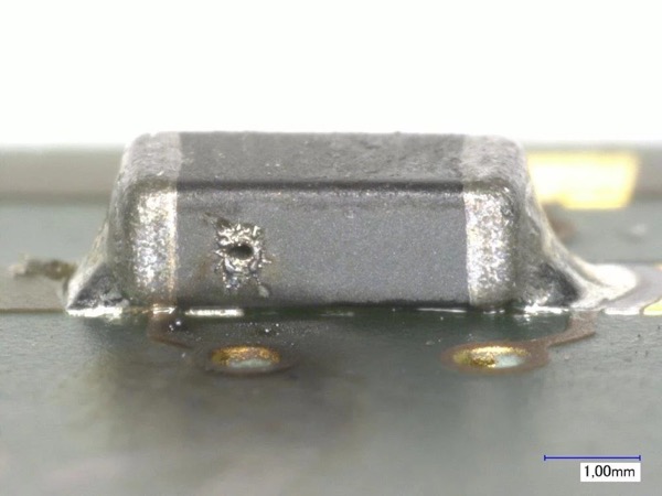
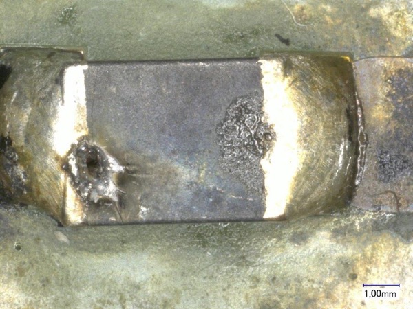

Figure 6: Melted and burned chip bead ferrites due to overcurrent and overheating
Such six devices would be needed for the positive input line and another six for the negative input line. This is not practical for several reasons: First, chip bead ferrites can be paralleled for continuous currents and their positive temperature coefficient will ensure that they share current more or less evenly. However, such current sharing is neither tested nor guaranteed for short-duration pulse currents. Second, placing several components in parallel with impedance that is dominated by resistance and inductance causes the inductance, the resistance and the impedance to drop, making them far less effective in filtering the desired noise. Third, six components cause high costs and need much PCB space.
Select the proper WE-MPSB
In situations where peak currents exceed average current by ratios from 3:1 to nearly 10:1, WE-MPSB are typically used. A first pass for selecting chip bead ferrites is to review all parts that can withstand the RMS current of 3.7 A.
Peak Current Proof Ferrites for the Input
In our application we are expecting 10 000 switching cycles during lifetime, so 10 000 pulses with 33 A will stress the WE-MPSB of the input filter and needs to outlast. The first step and most comfortable way is to enter these data into the pulse designer of REDEXPERT. There are 9 parts left, which we took all in the product storage for easy comparison.

Figure 7: Enter the pulse length, peak current and number of pulses
Validation of Effective Resistance
From the 9 left WE-MPSB, we now select the one with the highest resistance (not total impedance) at the noise frequency. In general, chip bead ferrites have their highest resistance at the frequency of their highest total impedance, but for other frequencies there is no general approximation possible. The fastest way to find the best part is using REDEXPERT from Würth Elektronik. As a registered user, you can place the chart slider at 170 MHz (see Figure 8) and read directly the resistance values of each part out of the grid. You can even sort descending to get the part with highest resistance.
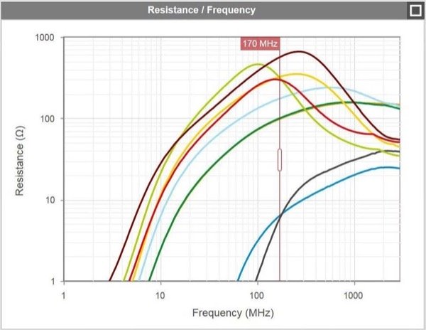

Figure 8: Determine the best suitable WE-MPSB with REDEXPERT leads to 742 792 245 51
Considering all of above parameters, the red highlighted part WE-MPSB 742 792 245 51 seems to be the best suitable component for our application. Its current rating is 4.0 A and it can withstand about 18 700 pulses of 33 A and 8 ms length. Keeping in mind that this 8 ms is much longer than the initial pulse of 500 µs and the short peak of 100 µs, gives it a plenty safety margin. From all suitable components, it is the one with the highest resistance of 170 MHz.
Pulse-Stable Ferrites for the Output
The output RMS current is the same as the average output current of 8.0 A. Following the same guidelines, there are five candidates rated for greater than 8.0 A:
All five parts can handle more than 10 000 pulses and have more than 8 A rms current rating, so the final selection will require actual EMC testing to determine which part filters the most noise. The smaller parts are less expensive but provide less reduction of noise.
Testing of the selected components
For final lab testing we added the above mentioned WE-MPSB 742 792 245 51 to the input and WE-MPSB 742 792 251 01 to the output. You can easily see that the green output voltage is now already silent.

Figure 9: Lab Results with Chip Bead Ferrites. The green output voltage is almost silent
Performing radiated EMI scan proves that the chip beads successfully suppress the PARD noise. Especially in the range of the 170 MHz PARD ringing, the EMI is significantly improved.


Figure 10: Lab Results of EMC-Testing. The user WE-MPSB chip beads significantly improve the radiated EMI in the range from 100 to 250 MHz >>
Influence of RDC to overall efficiency
The used WE-MPSB 742 792 245 51 has a DC resistance of 35 mΩ, which adds additional conduction losses and therewith reduces the efficiency. The measurements in our lab shown just a slight decrease of the efficiency from 95% down to 94.5% for each used chip bead ferrite. To investigate it in detail, we calculate the efficiency as follow:
Influence of DC Bias to Impedance Characteristic
As all magnetic parts, also chip bead ferrites follow the basic principles of elementary magnets in physics. With increasing DC current, it will continuously saturate up to the level of complete saturation. This effect shifts the impedance curve, as shown in figure 10. The peak inductance value remains almost constant with a drop of just 40% of its initial value, whereas the impedance at lower frequencies significantly drops by rates of up to 90%. In low frequencies, the inductive part is dominating, which saturates with DC current. Above the SRF (Self Resonant Frequency), the capacitive part is dominating, which is not affected by the DC current.
However, if you do your EMI measurements at full load current, this (worst case) impedance shift is already considered in your measurements and you don’t have to care about this effect. Important to know is that, the bigger the size of the chip bead ferrites, the lower is the fluctuation of impedance caused by DC current.

Figure 11: Impedance of WE-MPSB 742 792 245 51 with DC bias current from 0A to 4A
Why Chip Bead Ferrites?
Chip bead ferrites are the best components for reducing high-frequency noise above 10 MHz. In power supply layouts they must be placed as close as possible to the source of noise which can be the input and output connectors, to properly filter conducted EMI from the input and output wiring harnesses. This prevents conducted EMI from becoming radiated EMI. Being the first components and the last components in the chain exposes chip bead ferrites to heavy transient currents, and circuit designers can now select parts that filter noise with minimal impact to power efficiency and will handle large current pulses with excellent reliability.
This article originally appeared in the Bodo’s Power Systems magazine.
About the Author
Ranjith Bramanpalli works as a Product Applications Engineer at Würth Elektronik Group, where he is particularly skilled in the field of PCB design, electrical and electronics engineering. He earned his Bachelor's Degree in Electrical and Electronics Engineering at Jawaharlal Nehru (JN) Technological University located in Hyderabad, India. He then also acquired his Master's Degree in Electrical Engineering at the University of Massachusetts, USA.